tcpMDT
Draw Crosses - MDT26
 | Command to execute in the CAD |
|---|---|
Vertical menu | MDT26 > Utilities > Draw Crosses |
Ribbon menu | Utilities > Drawing > Draw Crosses |
Command line |
Draw Crosses
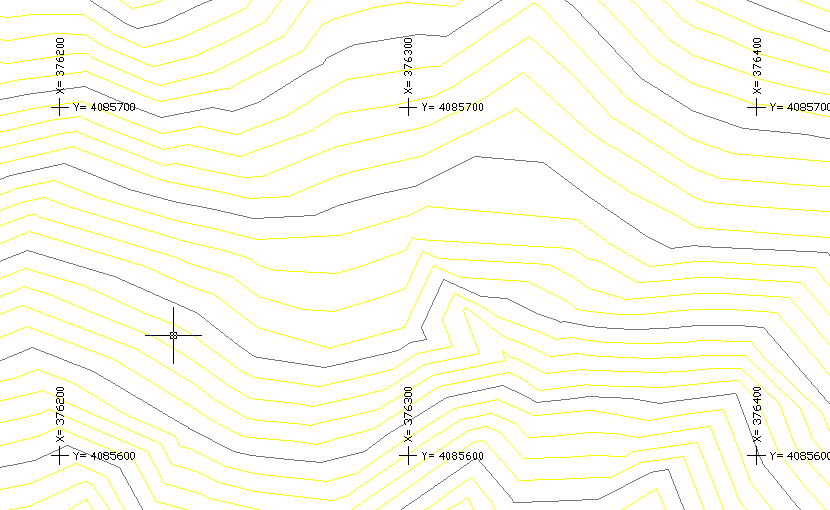
This option draws a set of crosses at coordinates with a set interval by specifying the distance between them and the distance between of X and Y coordinate labels. The CROSS and COORD blocks are respectively inserted. These blocks are in the Blocks folder located in the directory where the program has been installed.
Once the command is executed, MDT requests the coordinates that will set the limits of the crosses' drawing. Firstly, one should choose the bottom left-hand corner and then the top right-hand corner. The program will then display the following dialog box, where the different parameters for drawing crosses are set.
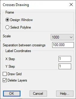
Frame: There are two options for drawing crosses:
Design Window: Select the ends of the window or frame.
Select Polyline: Indicate the polyline that will be used as frames for the drawing of the crosses.
Scale: Sets the scale of the drawing. The text sizes will be calculated on the basis of this value.
Separation between Crosses: MDT will label the crosses with the interval specified in this box.
X Labeling Interval: Sets the interval on the abscissa's axis with which one wishes to label the X values.
Y Labeling Interval: Sets the interval on the ordinate axis with which one wishes to label the Y values.
Delete Layer: If this option is activated, MDT will automatically delete any objects which happens to be in the same layer while drawing the crosses.
Once the dialog box is validated, it proceeds to draw the crosses.