
tcpMDT
Defining road section - MDT26
8.6 Defining Road Section
Before obtaining the complete cross sections, we must specify the road sections that will be associated with our road. The program initially incorporates a library of platforms, ditches, slopes and roadbeds, which can be expanded and customized.
On this occasion, we will use these elements, in order to facilitate the learning process.
Platforms
We start by selecting the option Templates> Create/Edit (or Templates> Create> Create/Edit), as a file we indicate solera.scc and the following window will appear, where we have a series of platforms available, which we can customize according to our needs.
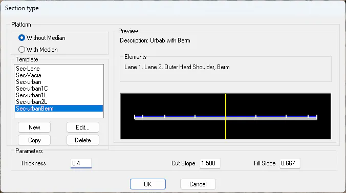
Select the Sec-urbanBerm template, check the option Without Median and press OK.
We observe that the pavement and the slopes of clearing and embankment will also be automatically assigned with the established values.
Next, it will ask us for the axis, which we can specify either by designating graphically or by means of a file.
Then the general window will appear for the definition of the types of elements that make up our section. A definition by default definition is shown, which we will then adapt to the needs of our road.
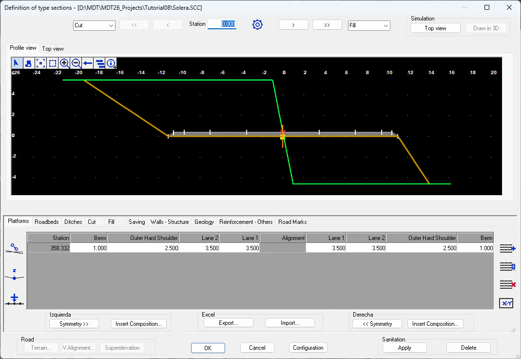
The idea is to define a symmetrical road, with a lane, an outer shoulder and a berm.
To do this, we will follow the following steps:
Initially, by default, a platform will be assigned up to the final PK of the axis, according to the selected template, for this we press the button 
Select the "Lane 2" column and with the right mouse button select the Delete option, this procedure is performed on the left and right of the axis.
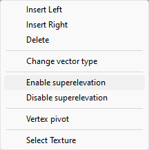
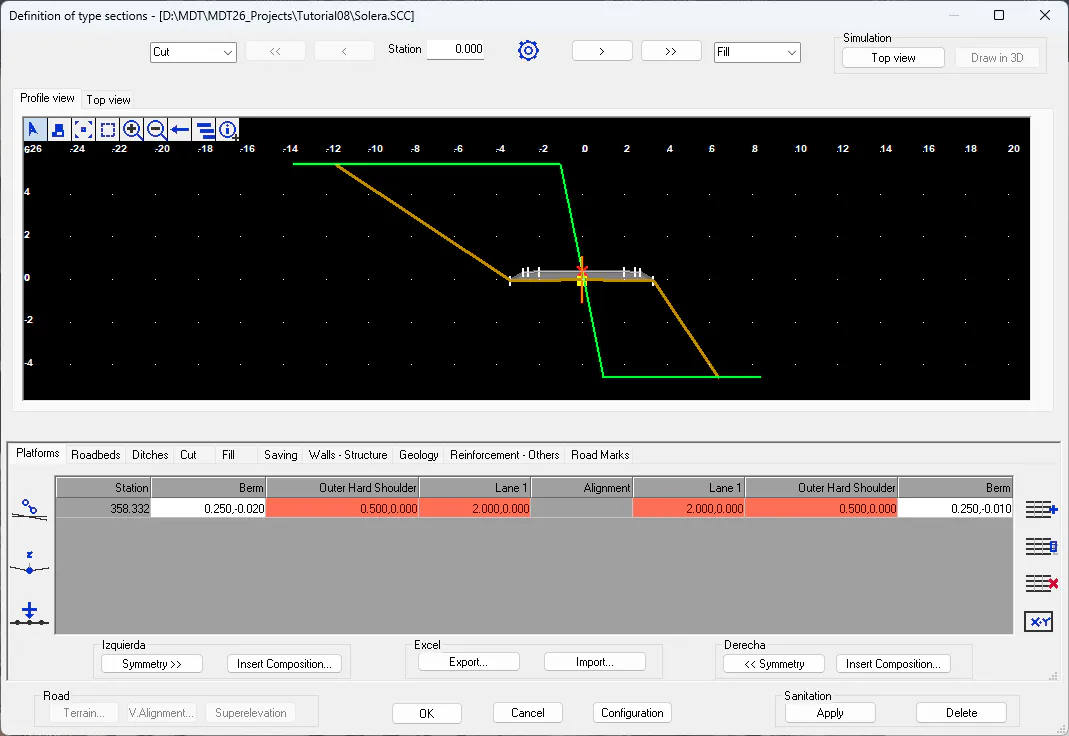
In the same way, we select the vectors "Lane 1" and "Outer Hard Shoulder" and indicate that both vectors are superelevatable, both to the left and right of the axis. We will observe that this situation applies because the cells take on the color red.
 We press this button and observe how in the cells, in addition to the X offset of the vector, the Y offset also appears.

In this situation, we assign the values to the "Berm" vectors:
DX = 0.25
DY=-0.01
We can enter the values separated by commas.
In the same way, we proceed with the assignment of the different values to the vectors according to the following capture.
Roadbeds
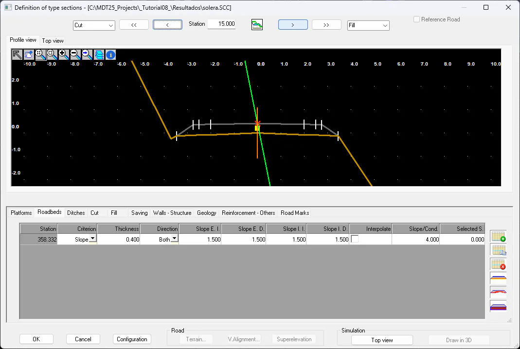
To modify the roadbed assigned by default, we activate the corresponding tab, and we will change the thickness of the roadbed for the value 0.4, the Criterion we will change it to Slope and the value of Slope/Cond. to 4.000. The final result will be the one that appears in the next figure.
Ditches
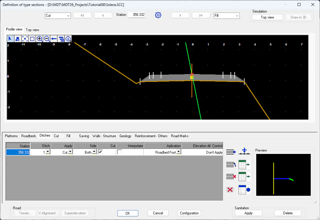
To define the ditch, click on the Ditches tab and press the Insert button. Then, you will see a set of ditches already defined, to which you can add new ditches or modify existing ones.
In this case we are going to use ditche nº 1, but we are going to modify the existing vector. We press the Edit button and assign the new vector the values 0.25 in X and 0.125 in Y.
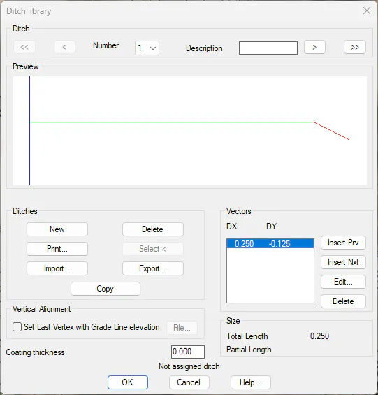
Once the window has been validated, it will ask us for the PK to which we are going to make the assignment. To do this, we activate the To Final Station. It will be possible to see how it is already drawn according to the characteristics indicated.
Cut and Fill Slopes
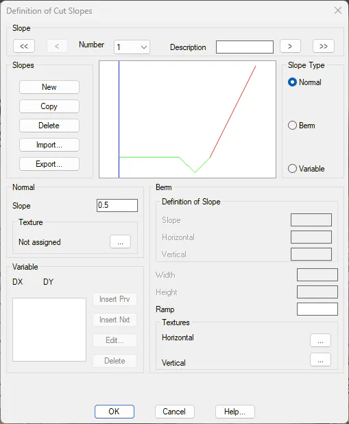
To define the clearing and embankment slopes, we are going to keep the embankment slope, but instead, we are going to change the clearing slope for a 0.5 slope.
To do this, we activate the "Cut" tab, remove the existing slope and add a new slope to which we will assign the value 0.5.
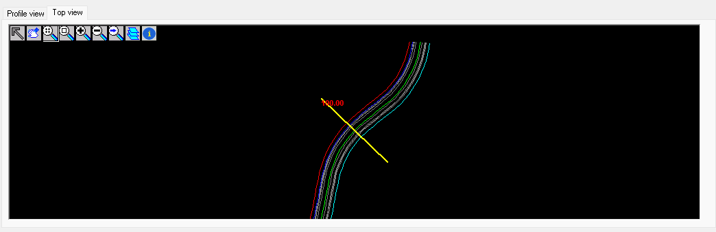
If we click on the Top View tab, we visualize in design time, how the road defined in the plan would look like. In this case, we have placed ourselves in station 100. Thus, we will represent it by taking station 100 of the alignment as a central reference, which can be visualized with a yellow line.
Press OK to leave the section definition command.