
tcpMDT
[PRO] Draw Pipes - MDT26

Draw Pipes
 | Command to execute in the CAD |
|---|---|
Vertical menu | MDT26 > Networks > Pipes > Draw Pipes |
Ribbon menu | Networks > Sections > Insert |
Command line |
This command will enable us to draw a pipe selecting the existing nodes in the drawing. To do so, there must be nodes in the drawing first.
When executing the command, the nodes through which the pipe to be created will pass through will be designated in sequence. Once all the nodes have been selected, the following window will appear featuring the characteristics of the section of piping to be defined.
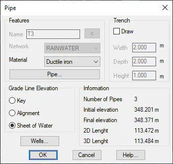
Features:
Name: The name of the pipe to be created. The name can be designated from existing text in the drawing.
Network: By default, the pipe network will be the same network as that of the nodes through which it passes.
Material: The type of material of the pipe. The Network Settings section provides us with the option of changing the materials to be used.
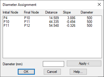
Tramos: We indicate the diameters of pipes between each of the nodes that make it up.
Grade Line Elevation: In this section we specify the point of application of the grade line in the pipe, consisting of three possibilities:
Key: The top of the pipe.
Alignment: The middle of the section of pipe.
Water depth: The bottom of the section of pipe.
Trench: the option of drawing the trench of the corresponding pipe with polylines. The characteristics of the same are provided below:
Width: The width of the trench.
Depth: The depth of the bottom of the trench in relation to the ground elevation.
Height: The height of the material between the bottom of the trench and the support point of the pipe.
Information: Displays relevant information on the section to be drawn, such as the initial elevation, final elevation, lengths ...
Wells: Clicking on this button will provide a list of all the nodes through which the pipe to be defined passes.
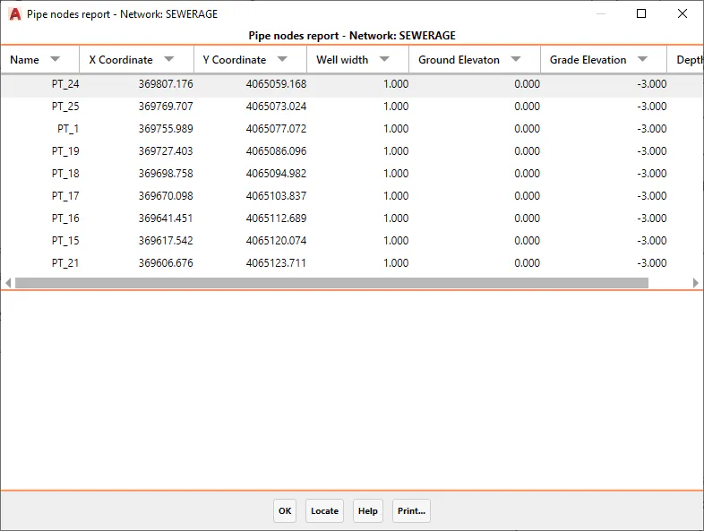
This list gives us the option of printing and locating any of the existing nodes.
Once we have accepted the drawing pipes window, if the software detects any intersection of the piping defined with the current surface (where applicable), the following window will appear, notifying us of such an incident and providing different options on how to proceed:
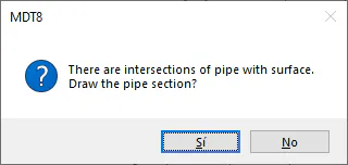
Label Intersection: The application will circle the points where the intersections have been detected.
Draw: We draw the section of piping despite the intersections in the terrain.
Cancel: We cancel the drawing of the section of piping.