tcpMDT
Draw Shadow Map - MDT26
Draw Shadow Map
 | Command to execute in the CAD |
|---|---|
Vertical menu | MDT26 > Maps > Draw Shadow Map |
Ribbon menu | |
Command line |
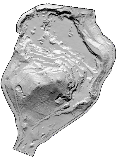
This tool will create an image that shows dark areas, i.e. those that are not directly illuminated by sunlight.
To do this, first of all we must establish as current the surface from which the calculation is going to be made and then we will be asked for the SRC (Coordinate Reference System) in which the drawing is located, finally the following dialog will be shown to configure the necessary parameters for the calculation of the shadows.
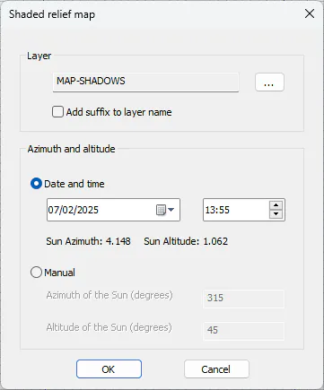
Layer: Layer on which the calculated image with the shadows will be drawn. If we select the Add suffix to layer name checkbox, the layer name will be assigned a suffix with the selected azimuth and time.
Azimuth and Altitude: The position of the sun is indicated by two different methods for the calculation of shadows.
Date and time: Date and time on which you want to perform the calculation.
Manual: We indicate the altitude of the Sun in degrees above the horizon and the azimuth.
As a result, an image will be generated with the surface name and suffix calculated based on the selected azimuth and altitude.