tcpMDT
Draw Slope Direction Map - MDT26
Draw Slope Direction Map
 | Command to execute in the CAD |
|---|---|
Vertical menu | MDT26 > Maps > Draw Slope Direction Map |
Ribbon menu | Maps > Maps > Slope Direction |
Command line |
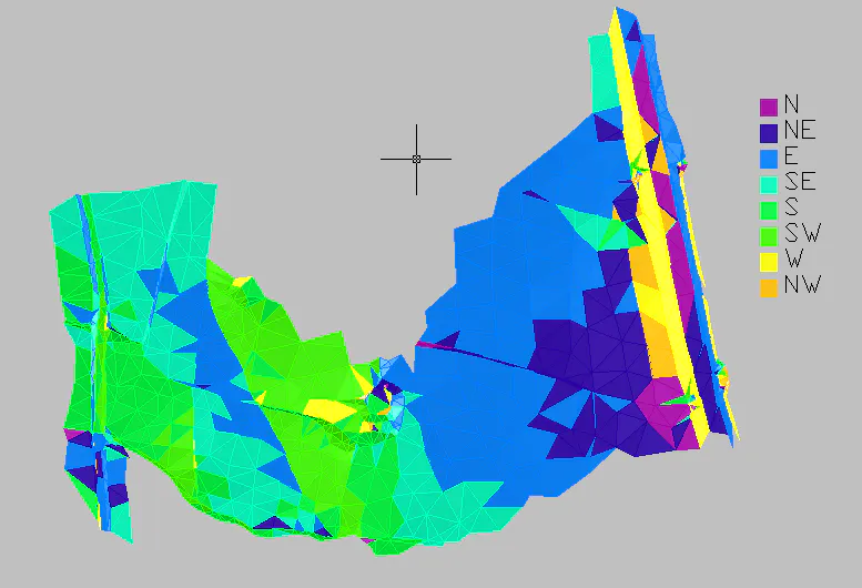
This command draws a map based on the current surface, assigning a different color to each triangle according to the orientation of its slope with regard to the cardinal points. The options available the same as the ones available in the Maps/Render > Draw Elevation Map command. The default interval and color configurations can be edited using the Map Configuration, Slope Dir. button.
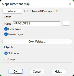
Objects: The drawing of the directions map can be executed as CAD 3D Faces entities or as an image.
If you select the Image mode, you can apply a transparency to it. An image will be created in TIF format that will have the name of the drawing with the suffix "slope_dir".
With this command, by contrast to the previous ones, the number of intervals cannot be customized, and the intervals will always be 8, coinciding with the 8 subdivisions of the cardinal points.