
tcpMDT
Create cross sections - MDT25
11.2 Create Cross-Sections
When this command is executed, cross-sections are obtained from 3D objects or MDT surfaces. There are different methods to obtain them. Initially, the program requests the horizontal alignment from which to obtain the profiles, which can be designated on the screen or by selecting the relevant file. The following dialog box then appears:
Surface: By clicking on this button, one selects the surface from which one wishes to obtain the profiles. Initially, the name of the current surface will be displayed. If a surface will not be used, this option is not necessary.
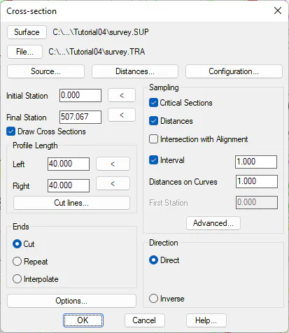
File: The cross-section information will be saved by default in a file with the name of the drawing and a .TRA extension. This name can be changed by clicking on the relevant button and selecting the file desired.
Source
By activating this button, one selects the data source from which one wishes to obtain the profiles --in other words, from an MDT surface, a set of contour lines, a three-dimensional grid, a road section file, etc.
The dialog box that is displayed when this option is executed appears below. It is commented on further below.
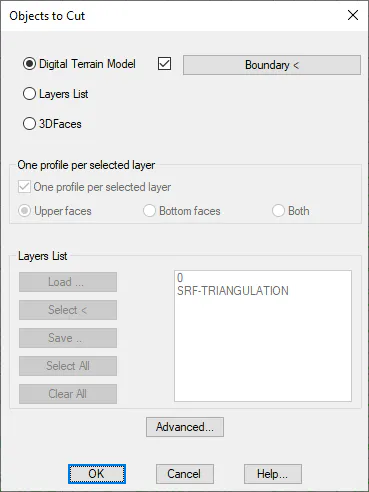
There are different options for obtaining cross-sections, depending on the data source one wishes to use in order to generate them. The different methods are described below.
Digital Terrain Model: Uses the surface generated by MDT as a data source. It should have been previously selected in the main dialog box. This option is advisable when the model has been correctly obtained, since it includes height and orientation towards break line information, making it possible to obtain an accurate intersection with all the elements.
Additionally, if we press the Boundary button there is the possibility of obtaining the profiles only from the surface contained within the selected polyline. For this, it is necessary that a closed polyline be designated.
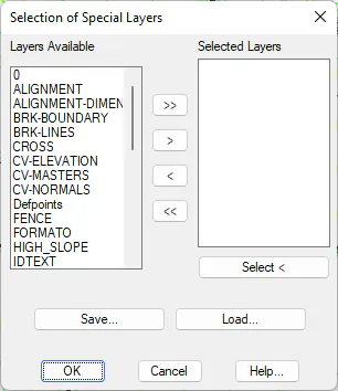
Layers List: This option allows one to cut any drawing element with elevation. In order to do so, the relevant layers whose elements are represented in 3D are selected using the cursor. The digital model can also be included in the selection by marking the TRI layer. Activating this option enables the Layers List box, from which the layers containing the 3D information can be selected.
In this latter option, if the name of an element's layer to be considered is unknown and its position in the drawing area is known, the Select button is simply clicked. At that moment, the program goes to drawing mode and the program requests objects to be selected. This operation should be executed for all of the elements selected.
The Save option is used when one wishes the set of layers to be saved in an ASCII file with the .CAP extension. The program superimposes a window called Save Layers List containing the project's directory and proposes the current drawing as a name, which can either be validated or changed. When validated, one goes back to the previous window. Once this operation has ended, one can understand the utility of the Load button, seeing as in all subsequent operations involving longitudinal or cross-section cuts the layers can be selected by clicking this button and selecting the name of the relevant layers file.
When this option is selected, the Advanced button is enabled, so that information on the objects associated to the layers is included when profiles are obtained from the layers selected in the dialog box shown below. Object heights are interpolated.
By activating the corresponding option in configuration, one can decide whether or not polylines with a zero elevation are to be cut.
3D faces: If we activate this option, we have the possibility to obtain the profiles from the 3d faces of the selected layers.
-
One profile per selected layer: If we select several layers and this option is activated, it will generate a cross-section for each of the selected layers. If the option is not enabled, it will create a single profile with all the information.
-
Upper Faces: At the generation level, only consider faces that are oriented upwards.
-
Bottom Faces: At the generation level, only consider the faces that are facing down.
-
Both: Consider the above two options for profile generation.
Initial Station: The initial station assigned to the horizontal alignment's initial position is entered in this box. The default value is either zero or the start of the horizontal alignment. Possibility to designate it graphically.
Final Station: The final station up to which one wishes to obtain the cross-sections is entered. Its default value will be the last station on the horizontal alignment selected. Possibility to designate it graphically.
Draw Cross Sections: If we enable this option, after successfully generating the cross sections the drawing thereof will be executed automatically.
Profile Length: The cross-sections' length is entered in this control by indicating the meters to the left and the right of the horizontal alignment.
Should the horizontal alignment or polyline from which one wishes to obtain the profile go beyond the area included in the digital model, its ends are interpolated from the last two vertices found before the first and last intersection in the model.
Additionally, there is the possibility of designating the distance graphically on the drawing with a line perpendicular to the alignment.
Cut Lines: This option allows one to set a series of polylines that will serve as a reference to calculate the ends of the cross-sections. The program will extend the cross-section until it finds an intersection with any of the polylines entered. The maximum extension length is as set in the Profile Length field.
Sampling
This text box displays a series of options to be considered depending on the cross-sections to be obtained.
Unique Points: When this option is selected, in addition to the previously determined constant interval distances, the program considers the initial and final stations and all the vertices found on the horizontal alignment, including changes of orientation, vertices when forming straight lines, tangents, etc.
Distance: This option allows one to include the cross-sections corresponding to specific stations. Activating this option enables the Distances button. A new window called Distances in Profiles is then displayed.
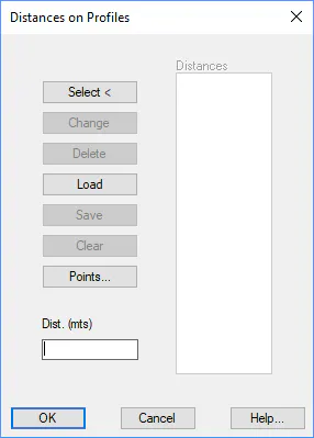
As can be seen, the window contains a series of buttons allowing one to edit the list of stations to be included.
Select: Allows one to graphically select the station. In order to do so, a point on screen is specified. The point thus chosen will be projected on the horizontal alignment and its distance with regard to the alignment's initial station will be found. If there is no projection, it will not be added to the list.
Change: This command changes the station selected from the list for the one indicated in the Distances text box.
Delete: Deletes the station selected from the list.
Load and Save: These commands load or generate a .DST file respectively, or a distance in profiles file where which each line indicates a station.
Clear: Deletes the entire list from the window.
Points: Provides access to the Point Selection window to determine the set of points whose stations one intends to project onto the horizontal alignment. (see Point Selection in the Points section).
Interval: This option allows one to extract cross-sections having the interval entered using this control.
Distance on Curves: The on-curve interval value with which one wishes to obtain the profiles is entered in this field
First station: This value indicates the horizontal alignment's first station from which the profiles will be obtained.
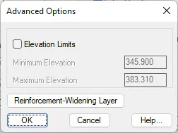
Advanced Options
The following parameters are configured in this group of options:
Elevation Limits: The Maximum Elevation and Minimum Elevation values to generate cross-sections are set. It is really a filter to avoid the existence of any elevations above or less than the ones entered.
Reinforcement-Widening Layer: Should there be the possibility of taking advantage of additional spaces in the road's definition, this command optionally allows one to select the layer where the polylines will be drawn to delimit the reinforcement or additional width areas.
Ends
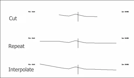
The program's behavior concerning cut ends of the cross-sections is set in this box when there is no terrain. Each of the options is described below:
Cut. Selected by default. It proposes the cross-sections to be cut should their strip width exceed the digital model's definition, or the objects selected, in which case the profiles take on a width equivalent to the width entered or up the point the model is defined.
Repeat. Using this option is recommended when there is excess strip width compared to the digital model and the surroundings are substantially similar to the last height obtained from the digital model. This is usually the case in terrain having large flat surfaces, or when curves in are cut a parallel fashion.
Interpolate. This option is used in order to complete the strip proposed when there is insufficient terrain in the strip width specified, the slope outside the working area is known and has similar gradients as those at the end of the profile. The program will interpolate using the slope of the last vectors cut until the height is raised to the profile's final length at the right-hand and left-hand sides.
.
Direction
This control allows one to specify the direction in which the profiles are to be obtained. Direct means in the direction of the horizontal alignment's definition, whereas Inverse means opposite to the forward direction defined.
Rendering options
These options allow one to configure how the cross-sections that will be obtained are to be represented.
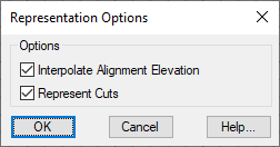
Interpolate Alignment Elevation: If this option is activated, the program will automatically generate a height on the horizontal alignment of each cross-section. If the source of the data is not an MDT surface, this height will be interpolated between the adjacent vertices.
Represent Cuts: When this option is activated and the cross-sections are obtained, it will draw the profiles obtained on the ground plan.
Results
There are various compulsory operations when entering cross-section data. One of them is to select the horizontal alignment. If it is not selected, the cross-sections cannot be obtained.
Additionally, if the digital model is not defined and no layer to cut or section or grid file has been selected, the "Layers not selected" error is displayed. Another possible error consists of not having found objects cutting the horizontal alignment. In this case, the error warning "No intersections found" is displayed
After all the data is entered in the dialog box, the program proceeds to draw all the cuts proposed (if the relevant option is activated) and information about the operation's progress is provided as a percentage. It then reminds one of the names of the file generated with a .TRA extension, in the project directory.
All the layers selected that are not visible will be reused and activated before this process begins, which is why it may be necessary to regenerate the drawing. If only the digital model is going to be cut, this is not necessary.
During the calculation process, heights are obtained from drawing objects and interpolating when necessary. There is also the possibility of cutting break lines even though they have been drawn on the plan. If the Draw Break Lines in 3D option of the Surface Configuration command in is not activated, the program assigns to each vertex the value of the point height coinciding with it.
Example: DEMO.TRA
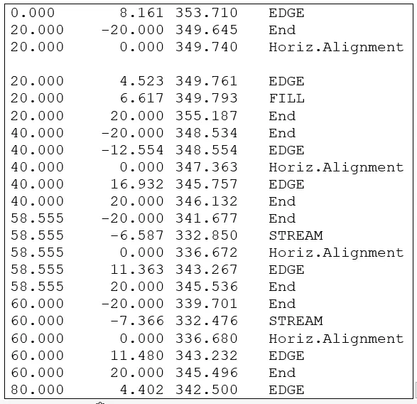
The file format consists of one line for each intersection found. The following appear on each line: station (taking the initial station into account), distance to the horizontal alignment (negative or positive, depending on whether it is to the left or the right of the horizontal alignment), the height of the terrain at that point and the name of the layer cut. This file can be drawn directly with the Draw Cross-Sections option.
In the aforementioned fragment of cross-sections made from a digitized cartography drawing, cuts with objects situated on different layers (fourth column) can be seen. Analyzing the stations, one can deduce that a distance of 20 m between profiles has been used and that the unique points have been included (station 58.555).
One can likewise observe that the Interpolate option has been used for the cuts. This can be seen because the observation "End" appears at the ends of each cut and because their heights are interpolated from the closest intersections. If the digital model had been defined, these heights would have been obtained from it whenever possible. When a profile is incomplete (there are only cuts on one side of the horizontal alignment), it is shown by an asterisk located in the first column of the line, so that the user can easily detect and correct such situations by editing the file or modifying the digital model. It can also be seen that the program always includes a line having the horizontal alignment's height for each cut, which is interpolated from the adjacent heights.