tcpMDT
Station the box is enabled by default and it shows the station or distance to or - MDT25
11.24 Station: The box is enabled by default and it shows the station or distance to origin.
Partial Distances: Indicates the distance with respect to the previous cut.
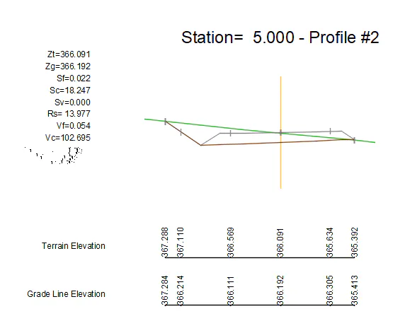
Terrain Elevation: Also enabled by default because it is of great help to configure the comparison plan at the intersection of the terrain with the horizontal alignment's position. This elevation is displayed with the "Zt=" prefix beneath the above-mentioned text. If the Numerical data option is activated, it appears as another element included in this data.
Grade Line Elevation: This box is only active when the profile file to be drawn comes from a segment file, in which case there is grade line information. It is displayed with the "Zr=" prefix. Similarly, if the Numerical Data option is activated, it appears as an element included in this data.
Subgrade Line Elevation: This option is only available in the case of selecting a segment and the subgrade is to be labelled at each cut, whenever the corresponding cut has an assigned roadbed.
Surfaces: Like the previous option, it is only active under the same conditions. Its text is positioned to the right of the horizontal alignment, symmetrical to the above-mentioned texts.
We can choose from the following drawings:
-
Cut area
-
Fill area
-
Topsoil area
The representation format is "CA=" for the cut area, "FA=" for the fill area and "TA=" for the topsoil area.
Volumes: Displays the calculation of the volume between the current station and the immediately previous one.
We can choose from the following drawings:
-
Cut Volume
-
Fill Volume
-
Topsoil Volume
The drawing format default is "CV =" for the cut volume, "FV =" for the fill volume and "TV =" for the topsoil volume.
Superelevations: Labels the superelevation to be applied both to the left as well as to the right of the station belonging to the segment to be drawn.
Coordinates: Option only available if we select a segment. The X and Y coordinates of the station will be labeled at the alignment position.
Elements to be labeled
Comparison plan: Features a horizontal line for each cut with a reference height.
Elevations on Profile: Displays heights on the terrain line at each of the points defining the cross-section.
Distances on Profile: Indicates the distances to the horizontal alignment beneath the terrain line at each of the points defining the cross-section.
Slopes in Profile: Shows the slopes of each of the vectors. Illustrated in each of the sections of the polyline. The value of the same is labeled per hundred.
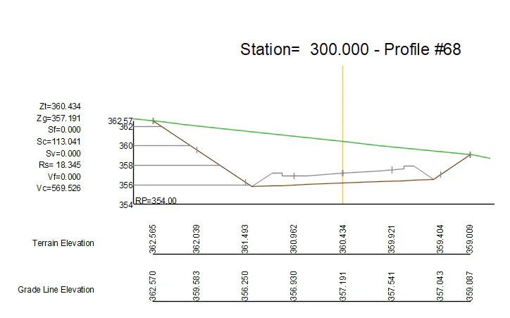
Numerical data: In this section the numerical data associated with the cross-section profiles is activated and configured: Terrain elevations, Grade line elevations, cut/fill, and codes, depending on whether a segment or a cross-section is selected.
Profile reference lines: This option will only be available if the Range is activated. When this option is activated, the marks on the profile will be extended to the comparison plane.
The following image displays a representation of a profile with associated numerical data:
Advanced
One can configure other profile drawing options using this command.
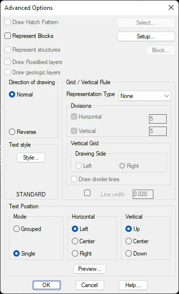
Draw Hatch Pattern: This option is only available for segment drawings. Should it be activated, it will draw a hatched pattern in the surface area to be measured cubically.
The hatch pattern can be selected by clicking on the Select button.
Represent Blocks: This option allows one to select the blocks one wishes to draw along with the cross-section.
If the Setup button is clicked, the following window is displayed where the insertion point of each of the blocks one wishes to insert along the different cross-section cuts is specified.
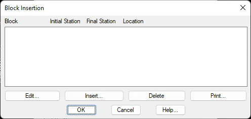
The following dialog box is displayed to insert or modify blocks in cross-section drawings.
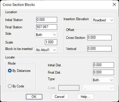
Everything concerning the definition and management of blocks is explained in greater detail in the Alignments >Blocks Definition section.
Represent Structures: If this option is checked, if there are structures in the segment definition, it will represent the block selected in the stations where the structure exists.
Group Elements: This option allows one to represent the set of cross-sections as if it were an AutoCAD block. This enables one to treat all the profiles as if they were a single object.
Draw Roadbed Layers: This option is only available for segment drawings. Should it be activated, the program will draw the roadbed layers associated to the cross-section defined if roadbed layers have been defined for it.
Draw Geology Layers: Only in the case of selecting a segment. If the segment has assigned geology, the different geology terrains will be drawn in the event this option has been activated.
Direction of Drawing: The possibility exists of specifying the way in which the cross-sections will be drawn.
-
Normal: The drawing is first made in columns and then in rows. The upper left-hand cut is the first station. (Direction of drawing top -- down).
-
Inverted: Likewise, columns are drawn first and then files are drawn. However, in this case, the initial station corresponds to the lower left-hand corner. (Direction of drawing bottom -- up).
Text Style: Select the text style to be associated with the texts labelling the cross-section drawing. By clicking on Styles any of the styles previously configured in CAD may be selected.
Grid: This option will enable us to draw a vertical grid or ruler associated with each cut to be drawn. The interval between the long marks and the short marks can be customized.
Selecting Vertical Ruler will enable us to draw it to the left or right of the profile. In addition, we have the option of drawing horizontal lines to join the dimension of the vertical ruler with the terrain. To do so, activate the Label division lines option.
Line Thickness: Indicates the thickness with which the cross-section lines will be drawn.
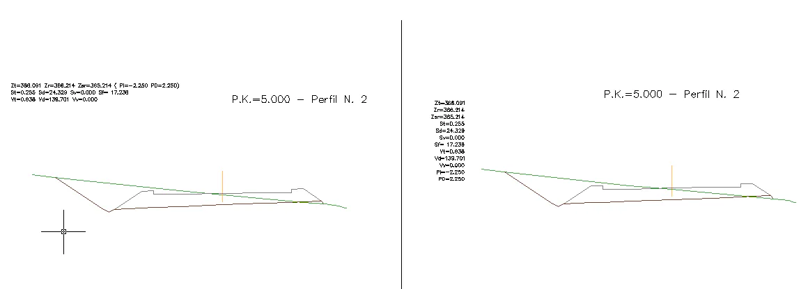
Position of Text: We can select the position in which the texts associated with each cross-section are to be labeled. They can be drawn in either horizontal or vertical format. Moreover, we can indicate their position for each option in the upper, middle or lower area of the corresponding profile.
Horizontal alignment Vertical alignment
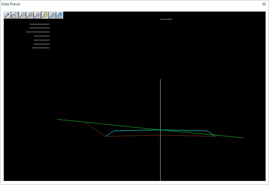
Preview: Selecting this tab will enable us to view the drawing of one of the profiles and the position of the texts.