
tcpMDT
Terrains - MDT25
11.23 Terrains
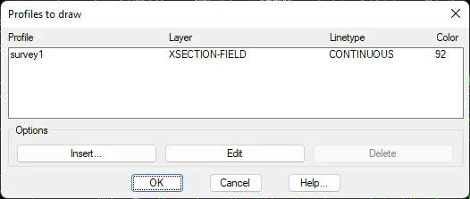
With this option you can manage the different terrains to be drawn. You will be able to simultaneously draw all the cross sections that are necessary, customizing the color, the name of the layer and the type of line for the representation of each cross section file.
Limits
Initial Station: The field shows the station from which the profiles are to be represented. It can be changed if one requires the drawing of profiles to start at a later station.
Final Station: This field, on the other hand, shows the last profile of the file selected. This value can likewise be changed if one wishes to end the list at station before the last one.
Critical Sections: Only available for the segment drawing and offers one the chance of choosing whether or not to draw the horizontal alignment's critical sections.
Interval: This option allows one to set the representation interval desired, as long as the cross-section stations to be drawn exist.
Spaces
If Model Space is selected, the profile's drawing will be drawn normally, that is to say from the initial point selected on screen.
Should Paper Space be selected, it will be drawn using the pre-set paper space option in CAD.
In the latter option, the program will assign a Title to each of the presentations it creates preceded by the "LON_" prefix and ending with an index corresponding to the number of sheets. For instance, LON_ROAD1.
Additionally, should a Paper Space already exist with the same name, the program will issue a warning that it already exists and ask whether the user wishes to delete it or create it again.
Format
Title: Once the profile is drawn, the title entered will appear on the top of the drawing.
Paper Size: This check box is used to select the size of the paper. One can choose among the different formats contemplated for distribution on sheets (defined in the HOJAS.DAT file). If one does not wish to split the drawing, the Continuous option (default value) should be selected.
It is possible to modify the name, size and contents of the formats proposed. In order to do so, the blocks in the BLOCKS folder of the program's root directory should be modified.
Concerning scale fields, it is necessary to consider that the drawing's scale is determined by text size in CAD, as the drawing is only generated on a scale of 1:1 and proportionally to the horizontal / vertical relation. The default value of both fields will be 1:200.
Horizontal Scale: This drop-down list displays all the scales defined in the ESCALAS.DAT file in the MDT configuration directory. It is possible to complete the list with other usual values.
Vertical Scale: Same as the previous paragraph. The possibility of defining a vertical scale on the cross-section drawing has been thought up to make it possible to observe height differences in very long profiles having very small height differences without having the need to continuously enlarge the drawing on screen.
Text Height: The value for the height of the texts that will be labelled on the cross-section drawing is entered.
If one selects a sheet format using scale control, the number of sheets and profiles per sheet to be represented on the drawing will be displayed.
Presentation
Rows and Columns: Both boxes are interrelated, depending on the number of profiles to be drawn. The initial values are calculated so that there is approximately the same number of rows and columns. If one figure is changed, the other will automatically be recalculated, so that the rows multiplied by the columns provides the approximate number of profiles. Both boxes are enabled with the continuous drawing option, because these values are automatically calculated when a sheet size is selected.
Label legend: If this option is activated an additional text will be labelled in the point selected by the user meaning that all the legends are labelled in the cross-section drawing.
Drawing Elements
Length and Height: The command will automatically calculate these values from the file selected. It represents the width and height of the element in which each of the cross-sections is drawn. It also displays minimum and maximum values that serve as orientation for the user when it comes to deciding the values of these parameters.
If these margins are considered excessive, (as they measure the module of each element of the drawing grid matrix), both values can be reduced, so that a higher number of profiles can be entered in the selected format.
Drawing Style
This option will allow us to save the drawing configuration in a file, therefore, the user will have the possibility to store different styles of representation of the profiles and select each of them as needed.

The operation would be as follows, initially the user would configure the style of representation he wants with all the options offered by the software, once selected, we press the Save button and store the information in a file.
Subsequently, with the Select button, we can select any of the files that have been previously created, with different drawing configurations, and automatically, the corresponding drawing and representation options will be recovered.
This tool would also be very useful, if we want to send our drawing settings to another user of the software.
Elements
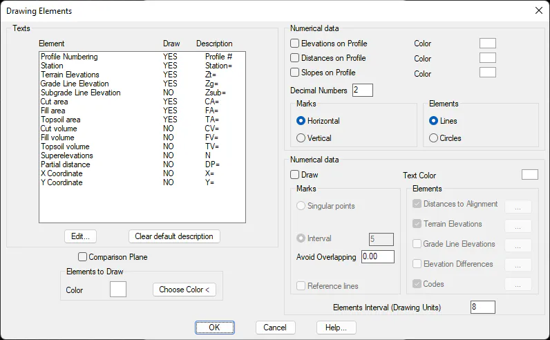
When this button is clicked, one accesses a new window where a series of profile characteristics the program can label on the drawing is displayed. The window in which these appear is shown below and a description of its characteristics appears further below.
Element
For each of the elements associated with the cross-section we have the option of indicating if we wish to draw it, in addition to the text as a prefix which will appear in the drawing of the profile.
Profile Numbering: When this box is activated, an increasing ordinal starting from the number one is displayed for each profile drawn.