
tcpMDT
[PRO] Check Superelevations - MDT26

Check Superelevations
 | Command to execute in the CAD |
|---|---|
Vertical menu | MDT26 > Roads/Segments > Superelevations > Check Superelevations |
Ribbon menu | Roads > Superelevations > Check |
Command line |
This application allow us to edit and visualize a super elevation file (per) and to also visualize the curvature's diagram from a horizontal alignment (eje file).
Once we run the application, we'll see something similar to this:
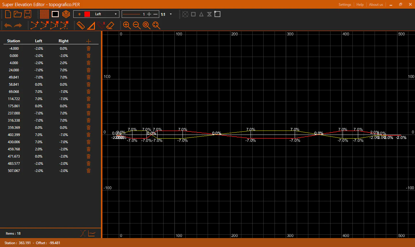
Along this document we are going to detail each of the parts, as a general overview we can distinguish multiple sections in the application's interface:
Title bar: At the top, the orange bar. The application's title appears at the left side. To the right we can find some options: Settings, Help and About us. Further to the right we have the usual window's controls: minimize, maximize/restore and close.
Toolbar: Just under the title bar. It allow us to manage the state of the view and to access to all the different edition tools.
Super Elevation's panel: Under the toolbar, to the left, we can see a panel with the super elevation's information.
CAD View: The application provides a CAD view in which the super elevation will be represented as polylines, it also allow us to take measures.
Status bar: At the window's bottom, the orange bar. It provides general information like the cursor coordinates in the drawing and information messages during the edition commands.
Settings
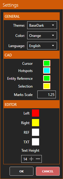
At the window's top right corner, we'll find a Settings button. When it's clicked the following dialog will show:
General
Theme: Defines the application's visuals. By default, it's settled as BaseDark so the application should have dark background and light foreground. The alternative would be the BaseLight theme which inverts the previous color scheme: light background and dark foreground.
Color: Defines the color palette used by the application. By default, it's settled to Orange. It can be stablished from a variety of colors.
Language: Allow us to choose the application's language
CAD
Cursor: Sets the color of the CAD view's cursor. This cursor it's only visible when there's an edition command active.
Hotspots: Sets the hotspots color for the selected entities in the CAD view.
Entity Reference: Sets the color for the entity reference marks in the CAD view when it's doing an operation which uses those references.
Selection: Sets the color for the selected vertices in a CAD view's entity.
Marks Scale: Sets the size scale for the CAD view's marks hotspots and entity references.
Editor
Left: Default color for the left super elevation's layer's polyline.
Right: Default color for the right super elevation's layer's polyline.
REF: Default color for the reference's line's layer, that marks the 0% super elevation location.
TXT: Default color for the texts layer.
Text height: Sets the texts size.
Toolbar
In the toolbar we find all the controls that allow us to manage the CAD view and the super elevation edition:

File Menu
With the file menu's controls, we can create new super elevation files, open existing files or save the changes of an edited super elevation:
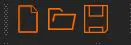
 New: Creates a new super elevation file. It will ask for a path for the new super elevation file and it will set it as the active one.
 Open: Asks for a per or eje file and adds it to the panel and the CAD view.
 Save: If there's an active super elevation, by default it will ask for a path to store a new per file with the actual data of the super elevation: if it has been modified those modifications will be stored, otherwise the file will be an exact copy from the original. If the output's file extension is changed, or there's no active super elevation when the button is clicked, the following options will be presented:
Save as dxf: Saves the current drawing in the CAD view in a dxf file. This includes polylines and measures drawn by the user.
Save as jpg: Allow us to store a georeferenced screenshot of what is currently visible in the CAD view. To adjust the screenshot settings the following dialog will be shown:
Take Screenshot
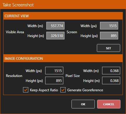
Current View
Visible area: Shows the screen size in meters and pixels.
Set: On click, we enter in a zoom by window command that we can use to set a region in the drawing.