
tcpMDT
[PRO] Road. Pro Generate Proposed Terrain - MDT26
Generate Proposed Terrain
 | Command to execute in the CAD |
|---|---|
Vertical menu | MDT26 > Roads/Segments > Generate Proposed Terrain |
Ribbon menu | Roads > Utilities > Export Proposed Terrain |
Command line |
This command generates the modified terrain associated with a previously defined segment (see Define/Edit Segment command).
First, the program requests the segment file from which to generate the profile, and then the following window appears to manage the type of modification to generate and last, the name of the cross-section file to generate.
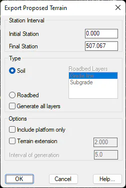
Station Intervals
Initial station: This facilitates selection of the initial station from which to calculate the modified cross-section.
Final station: Final station up to which the modified terrain will be generated.
Type
Soil: The modified terrain will be generated taking only the subgrade into account if roadbed is defined. If it is not defined it will directly generate on the vertical alignment.
Roadbed: It only makes sense to select this option if the section of our road has roadbed assigned, in which case if there are roadbed layers associated with it the layer that we wish to account for in generating the terrain must be selected.
Roadbed layers: This lists the data on the roadbed layers associated with the road. Select the one that must be accounted for when generating the modified road.
Generate all layers: If several layers are associated with the roadbed, if this option is activated, the program will automatically generate a cross-section for each of the layers of associated roadbed. The cross-section will take the name of the cross-section output file selected, giving it the name of the corresponding roadbed layer as a suffix.
The pavement layers associated with the auxiliary vectors, such as sidewalk and parking, will also be included. If the same layer exists for the same vector on opposite sides, a suffix with L or R will be added to the cross-section file name depending on whether the vector is on the left or right, respectively.
Options
Include Platforms only: If this option is activated, when generating the modified terrain or any of the roadbed layers, in the final cross-section it will only create the vertices corresponding to the platform, omitting those that correspond to other section elements, whether ditches, slopes, walls, etc.
Terrain extension: If this box is checked, it will indicate the amount of terrain to exceed the profile. If, on the contrary it is not checked, it will represent the entire profile. This option only affects the graphic representation, not the surface calculation.
Interval of Generation: If the segment selected has no natural terrain associated, in this field we define the interval of generation of the modified terrain. In this case, the information on each of the cross-section cuts generated will only include those corresponding to the platform.
Once the dialogue box is validated the modified terrain is generated. This file is processed as if it were another cross-section file, with commands to check, draw, etc. -- the list given previously.
Generation Errors
After generating the modified terrain, the following window will appear detailing the different errors found. These errors are classified as "Warnings" or "Errors" depending on their degree of influence on the road definition. In the former the road has been generated and in the latter its composition is impossible in the station specified.
The following displays the error window that appears after the generation process.
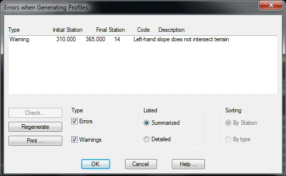
The list displays the error report and at the bottom are the different classifications.
Errors: The list only displays the errors found during the generation process.
Warnings: In this case it only shows the warnings.
Summarized: Displays the list grouped by stations with the same type of incident.
Detailed: A station-by-station list of the errors found at each station.
By clicking on the Check button (only if Detailed is checked), the command corresponding to the error found is activated and any changes necessary can be made. If the Regenerate button is then clicked, MDT will calculate the new segment.
It will then display a list of different possible errors and their error category.
Station not generated. No intersection with terrain
Cause: When generating the cross-sections, the corresponding cut was not created as the objects selected are not cut.
Solution: Check whether the drawing or horizontal alignment is correctly defined.
Left/right-hand slope does not intersect terrain
Cause: When assigning the slope that cuts the natural terrain with a code, the code entered is not found in the terrain.
Solution: Check slope assignment to see if the code entered is correct.
Too many vertices on slope
Cause: The slope's definition contains too many vertices.
Solution: An erroneous height difference may exist between the grade line and the natural terrain, thereby creating an excessive number of berms on the slope.
Too many vertices in ditch
Cause: The ditch's definition contains too many vertices.
Solution: There may be an erroneous height difference between the grade line and the natural terrain.
Slope assigned does not exist
Cause: A slope has been assigned which has not been previously defined.
Solution: Execute the Sections > Definition of Slopes command and define the appropriate slope.
Platform assigned does not exist
Cause: A platform has been assigned which has not been previously defined.
Solution: Execute the Sections > Definition of Platforms command and define the appropriate platform.
Left/right roadbed creation error
Cause: MDT has detected an error when generating the roadbed associated to the section type at the specified station.
Solution: Check in Sections > Definition of Roadbeds the roadbed assigned to the station in question and the criterion defined.
Cross-section definition does not exist
Cause: The natural terrain associated to the segment contains no information or is corrupt.
Solution: It would be advisable to obtain the profiles associated to the work again. In order do so, execute the command Cross-Sections > Obtain Profiles.
Geology assignment not found on left/right slope
Cause: The definition of the terrain's geology associated to the definition of the section's slope does not exist or is incomplete.
Solution: Execute the Templates > Assignment of Templates to Horizontal Alignment command, activate the Geology option and configure it properly.
There is no left/right slope assignment
Cause: No slope assignment has been defined.
Solution: Execute the command Templates Type > Assignment of Templates to horizontal alignment
and configure slope assignment at the stations where the problem appears.
Vertical alignment does not exist
Cause: The segment has no grade line information associated to it.
Solution: Execute the Vertical Alignment > Define Vertical Alignment command and insert it in the segment.
Platform assignment does not exist
Cause: The platform has not been assigned to the section template.
Solution: Execute the Section Template > Assignment of Templates to Alignment command and assign the relevant platform to the station concerned.
Platform not found
Cause: MDT is attempting to assign a platform to a station, which has not been defined or has been deleted.
Solution: Execute the command Templates > Definition of Platforms and define the appropriate platform for the station.
Station does not exist on alignment
Cause: The station it is trying to process is not defined on the horizontal alignment.
Solution: The horizontal alignment associated to the segment may contain corrupt information or the segment may have a horizontal alignment assigned that does not correspond to it.
Generation Warnings
The ditch assigned does not exist
Cause: A ditch that has not been previously defined has been assigned.
Solution: Execute the Template Types > Definition of Ditches command and define the appropriate ditch.
Station does not exist on the vertical alignment
Cause: The station interval defined on the grade line is less than the one defined in the natural terrain.
Solution: Execute the Vertical Alignment > Define Vertical Alignment command or the Vertical Alignment > Edit Vertical Alignment commands and check the grade line.
Left/right-hand slope does not intersect terrain
Cause: One or several slopes have been assigned which do not cut the terrain. The problem may lie in the fact that the natural terrain is narrower that the cross-section template defined.
Solution: Obtain the cross-sections again with a left/right-hand width greater than before or modify the slopes' gradient.
Terrain to the left/right shorter than platform
Cause: A platform has been assigned which is wider than the natural terrain in the segment.
Solution: Obtain the cross-sections again with a left/right-hand width greater than before.
Left/right-hand ditch assignment does not exist
Cause: No ditch assignment has been defined for the station specified.
Solution: Execute the command Templates > Assignment of templates to horizontal alignment and assign the appropriate ditch.
Roadbed assignment does not exist
Cause: No roadbed has been assigned for the station specified.
Solution: Execute the Templates > Assignment of Templates to Horizontal Alignment command and assign the appropriate roadbed.
The roadbed assigned does not exist
Cause: A roadbed that has not been previously defined has been assigned.
Solution: Execute the command Templates > Definition of Roadbeds and define the appropriate roadbed.
Median element assigned does not exist
Cause: A median element that has not been previously defined has been assigned.
Solution: Execute the Template Types > Definition of Elements command and define the appropriate median element.
Median element assigned does not exist
Cause: A median element that has not been previously defined has been assigned.
Solution: Execute the Template Types > Definition of Elements command and define the appropriate median element.
Insufficient median width
Cause: Either median width is incorrect or, on the contrary, the median element defined is too wide.
Solution: Check both the median's definition in definition of platform as well as the definition of the median element assigned.
There is no correlation in code assignation
Cause: The platform's vector codes may have possibly not been correctly assigned in the platform's definition.
Solution: Check that the vector codes of the platforms assigned have been correctly assigned.
There is no information on the left/right-hand side profile
Cause: The cross-section has not been generated on one of the horizontal assignment's sides.
Solution: Check that information does not really exist about the objects to be
cut in the side affected.