
tcpMDT
[PRO] Superelevations Table - MDT26

Superelevations Table
 | Command to execute in the CAD |
|---|---|
Vertical menu | MDT26 > Roads/Segments > Superelevations > Superelevations Table |
Ribbon menu | Roads > Superelevations > Table |
Command line |
On executing this command, the program will show a window with the existing superelevations tables in accordance with the country selected under settings.
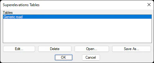
Delete: Removes the superelevations table selected.
Open: Enables us to select a new superelevations table to insert in the list. The Generate Superelevation from Alignment command will activate all the tables we have configured in this section.
Edit: Enables us to edit the superelevations table selected. This window contains a list comprising the Radius, Slope in % and Minimum Clothoid Length columns to be applied to the previous ones. The minimum length is used to calculate the recommended value of the parameter for each radius in accordance with the Road Instructions. See the Personalization Manual for more details.
Optionally, the table may be modified or customized depending on the road design characteristics and the speed assigned to them. The superelevation file is initially requested. Then a dialog box is displayed showing the file's configuration. Each of the superelevation tables may have different values according to the road design's speed. The features of the dialog box are described below.
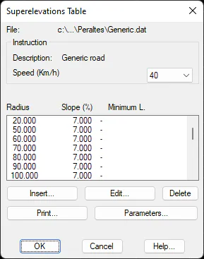
Description: Shows the description of the superelevations table selected.
Speed: Offers the possibility of selecting among the different speeds available in the superelevations table selected.
Insert and Edit: Any of the records appearing in the superelevations table may be entered or modified. When any of these buttons is activated, the following dialog box is displayed, where the changes are made.
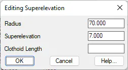
Delete: Deletes the record marked on the list from the table.
Print: Transfers the information on the superelevation table to the system's printer or to a file.
Parameters
A series of values which are needed to generate and process superelevations are configured in this window. The dialog box and its parameters are shown below.
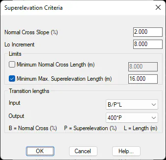
Normal Cross Slope (%): The normal cross slope expressed as a percentage for straight sections which is proposed by default is entered here. It is normally 2 %.
Lo Increment: The camber transition length to 0% and from 0% to slope are set here, which is applied before and after the origin of L~0~.
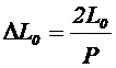
Minimum Normal Cross Length: When activated, this box will apply the criterion of setting at least one straight section length with camber. This is indicated by the values entered in the adjacent box. This parameter analyses the length that results between transition curves and, if the difference between the start of the cambered section and its end is below the established value, the camber is cancelled. In the case of curves having same sign, superelevation continuity is set at 2% (in the case of curves of the same sign), otherwise the devil effect is produced at the center of the straight section (in the case of curves having the opposite sign).
Minimum Length of Maximum Superelevation: As with the previous element, when this command is activated, it will require that a section of maximum superelevation should remain (the maximum established by the radius and superelevation table) once the L~0~ lengths have been applied towards the inside of the curve from its entry and exit tangents. The minimum length this section is equal to or greater than the length set in the relevant box. Should a lower value be produced, the program will modify the L~0~ value until it is able to apply the criterion set out above.