tcpMDT
[PRO] Draw Superelevation - MDT26
Draw Superelevation
 | Command to execute in the CAD |
|---|---|
Vertical menu | MDT26 > Roads/Segments > Superelevations > Draw Superelevation |
Ribbon menu | |
Command line |
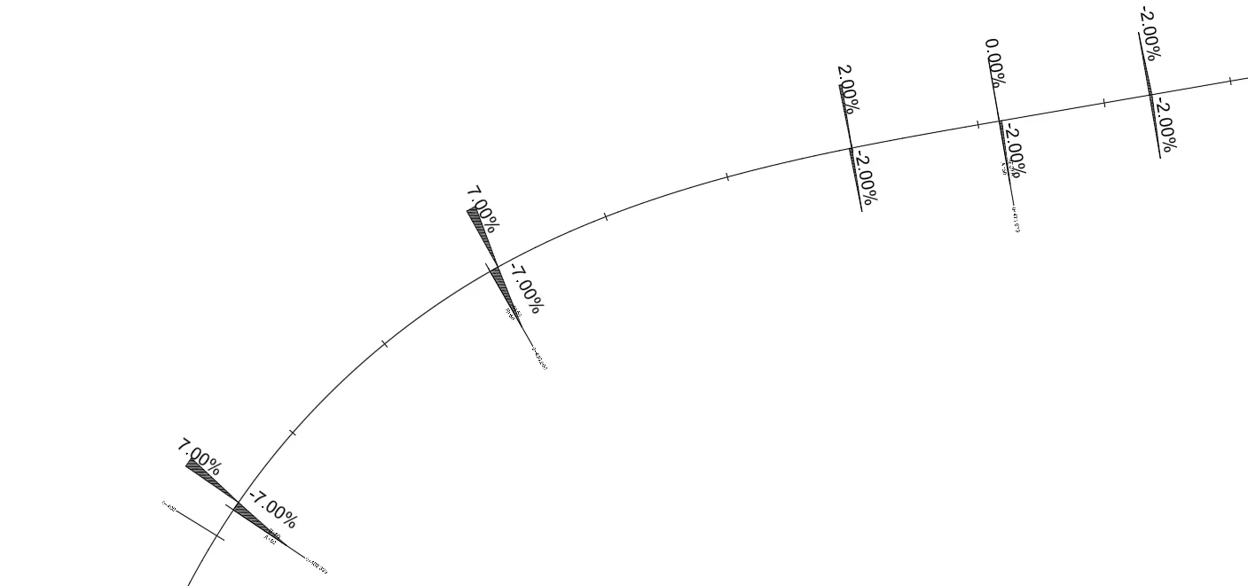
This option allows the superelevation values at each station to be displayed in plan view alongside the alignment.
First, the user is prompted to select the alignment, after which a dialog box appears for configuring the superelevation representation in plan view.
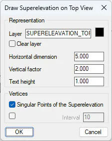
Layer: Defines the layer where the entities associated with the superelevation values will be drawn.
Clear Layer: Before drawing, all entities contained in the selected layer are deleted.
Representation
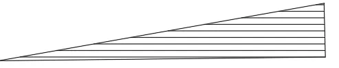
Horizontal Dimension: Defines the horizontal length of the marker representing the superelevation.
Vertical Factor: Multiplication factor applied to the height of the symbol representing the superelevation.
Text Height: Defines the height of the text labels displaying the superelevation percentages.
Vértices
Superelevation Critical Points: When enabled, labels appear at stations linked to the selected superelevation.
Interval: When enabled, superelevation displays at the specified interval.