
tcpMDT
[PRO] Road Intersections - MDT26

Road Intersections
This section describes a set of tools which will help us build the horn intersection between two roads.
To execute the intersection, the different commands are positioned in the menu in the order to be executed. Additionally, these same options can be run from the Projects window.
For each of the speakers a segment will be created, it will be built automatically as we execute the different commands of the intersection.
Intersections Menu | Project Window |
|---|---|
 |  |
 |
Before starting the calculation, it is necessary to Generate Proposed Terrain of the two roads that intervene in it, leaving the area of action of the intersection unmodified.
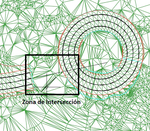
Create Link
 | Command to execute in the CAD |
|---|---|
Vertical menu | MDT26 > Roads/Segments > Road Intersections > Create Link |
Ribbon menu | Roads > Intersections > Create Link |
Command line |
It is the initial command, where we will indicate the segment corresponding to the Main Road and the Secondary* Road***. The following window will appear in which, graphically you can see the function of each road.
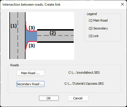
When validating the dialogue, it will ask us for the points of tangency in the main and secondary segment, these points of tangency will correspond to the beginning and end of the link.
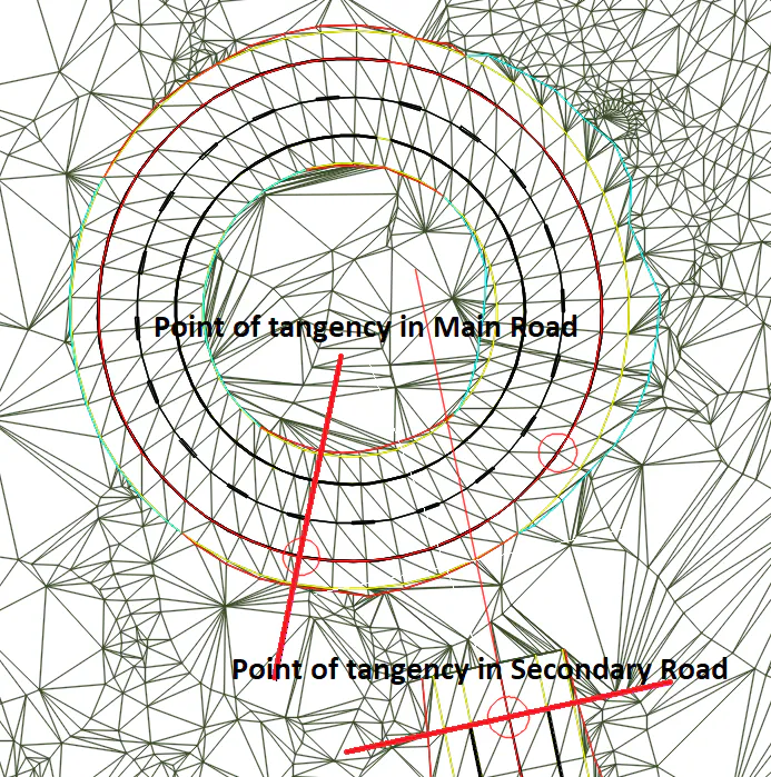
Once the points of tangency have been designated, the following window will appear in which we define the alignment of the corresponding side.
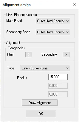
Link. Platform vectors: We indicate the coupling vector of the link alignment, both in the main and secondary roads.
Tangents: Possibility to change the position of the tangency points selected in the previous point.
Type: Type of alignment. It is possible to select three options:
Line -- Curve -- Line: We define an alignment with a circular one between two lines. Request the radius of the circular.
Clothoid -- Curve -- Clothoid: In this type of alignment we specify the parameter of the input clothoid, the radius of the circular and the parameter of the output clothoid.
Designate: In this case, we have previously defined an axis or polyline that represents the alignment of our horn, it will ask us to designate it.
Draw Alignment: For types 1 and 2, when pressing the button, the alignment will be drawn with the indicated parameters, this option gives us the possibility of performing different tests until reaching the appropriate alignment.
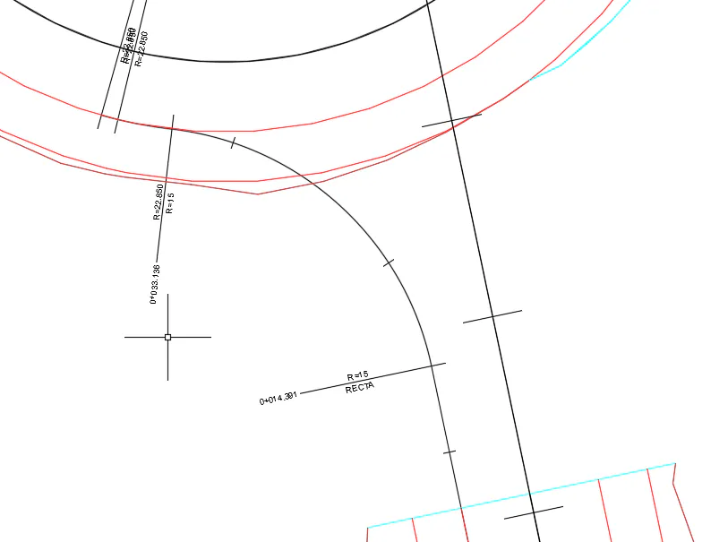
When validating the dialog, the alignment will be drawn automatically and a segment with the alignment will be created. It is on this segment that the following commands will be worked. By default, the segment name will be constructed from the name of the parent and secondary segment and the action side.
Calculate Vertical Alignment of Link
| Command to execute in the CAD |
|---|---|
Vertical menu | MDT26 > Roads/Segments > Road Intersections > Calculate Vertical Alignment of Link |
Ribbon menu | Roads > Intersections > Grade Line |
Command line |
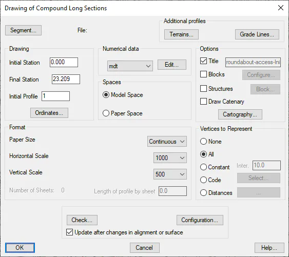
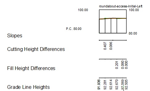
In this step we are going to define the vertical alignment that we have defined in the previous step, for this. Once the command is executed, we select the alignment of the link and a vertical alignment will be created automatically, with a vertex in the intermediate station. This will be automatically inserted into the segment of our link.
 |  |
|---|---|
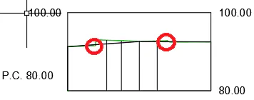
Now, on the drawing of the vertical alignment, we must insert or modify the vertices of it so that it adapts perfectly to the main and secondary road (red circles). For this we have the tool Vertical Alignment > Vertical Transition Curve.
Calculate Cross-sections of Link
| Command to execute in the CAD |
|---|---|
Vertical menu | MDT26 > Roads/Segments > Road Intersections > Calculate Cross-sections of Link |
Ribbon menu | Roads > Intersections > Cross Sections |
Command line |
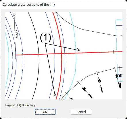
With this option, we will insert, in the segment of the link, the cross-sections of the current state of the surface. Once the command is executed, it will ask us for the alignment of the link in which we are working and then we will have to select the border lines, that is, the polylines to which the profiles will be generated, these will delimit the area of action of the link. As a help, the following window will appear indicating the location of these border lines.
Once the lines are designated, the cross-sections generation dialog will appear. In it it would be necessary to specify a Profile Length to the left and right sufficient to include the entire area of action. It is also convenient to apply a small generation interval so that the cross-sections to be created have the maximum resolution.
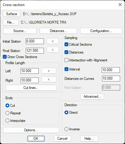
Once the dialogue has been validated, the crossbars will be automatically inserted into the segment of our link.
Calculate Section of Link
| Command to execute in the CAD |
|---|---|
Vertical menu | MDT26 > Roads/Segments > Road Intersections > Calculate Section of Link |
Ribbon menu | Roads > Intersections > Road Section |
Command line |
With this option, finally, we will define the road type section of the link. For this, initially it asks us for the reference polyline in the main road. Once designated, we move on to the definition of the type section.
A section will be created that represents the characteristics of the link. In this case study, we would have an outer hard shoulder on the left and a lane on the right.
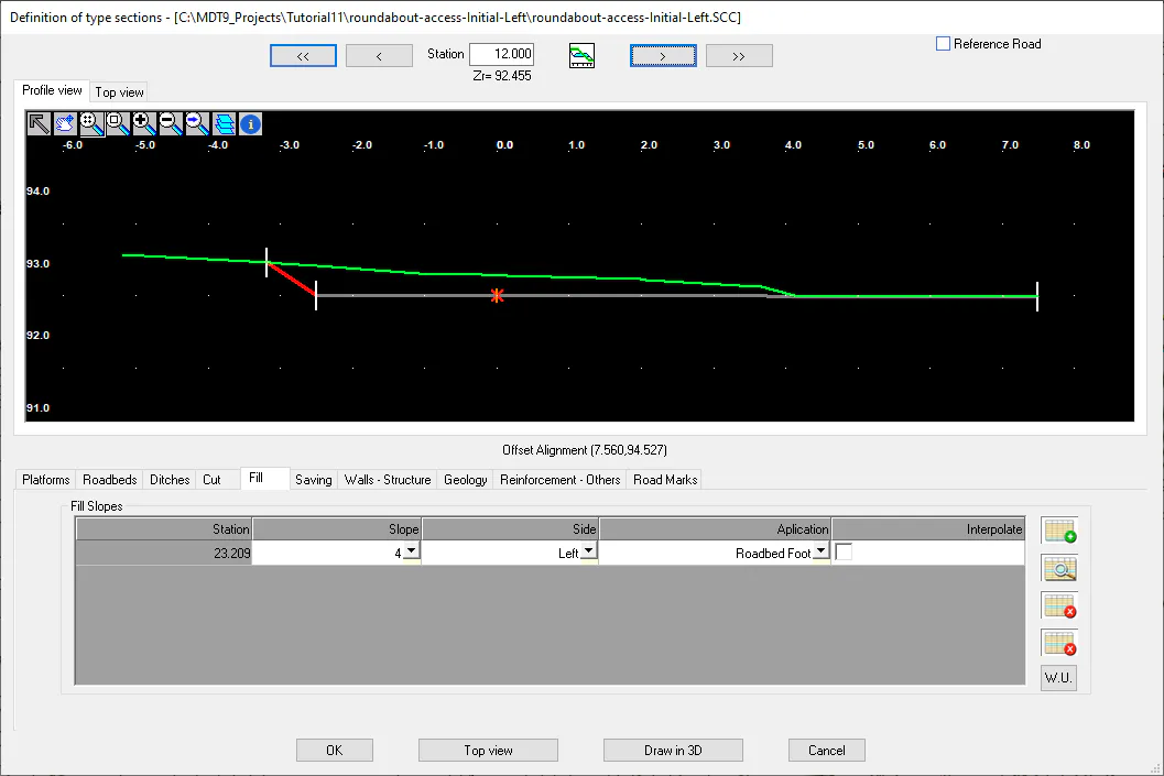
In addition, depending on the link on the left or right, we will indicate that only cut and fill slopes are applied on the outer side of the link.
When you accept the section definition window, it will automatically be incorporated into the link segment.
Draw Link
| Command to execute in the CAD |
|---|---|
Vertical menu | MDT26 > Roads/Segments > Road Intersections > Draw Link |
Ribbon menu | Roads > Intersections > Draw Link |
Command line |
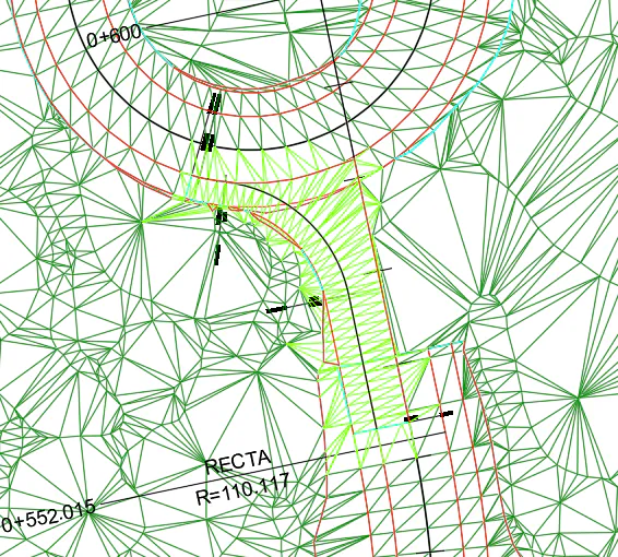
Finally, with this option we obtain the modified horn as well as the new surface. Once the option has been executed, it will ask us to graphically designate the alignment of the link and then the window will appear to configure the obtaining of the modified terrain.
In the User Manual, an exercise has been created focused exclusively on the creation of a road intersection. Specifically, we can find them in Tutorial 11.