
tcpMDT
[PRO] Earthworks by Terrain Elevation - MDT26

Earthworks by Terrain Elevation
 | Command to execute in the CAD |
|---|---|
Vertical menu | MDT26 > Surfaces > Grading > by Terrain Elevation |
Ribbon menu | Surfaces > Grading > Terrain Elevation |
Command line |
Along with Earthworks by Platform Elevation, this tool allows one to change the current surface by creating a platform. It is supposed that either the external slope area, the elevation one wishes to reach or the resulting volume after the platform is created is known.
Firstly, one has to designate the closed polyline defining the contact area's boundary. The following dialog box is then displayed:
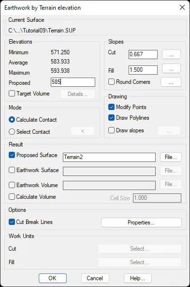
The upper part displays the name of the current surface and its elevations along the polyline selected are displayed on the left. One then has to specify the following parameters depending on the option chosen in the Mode box.
Calculate Contact: The crowning elevation of the platform to be created has to be entered in the Proposed box. Additionally, the percentage gradients of the cutting and fill slopes also have to be entered. The Discretization parameter controls the interval between each slope projection. The lower this parameter is, the longer the command will take. The option Round corners is used to decide on the behavior of the slope in convex vertices.
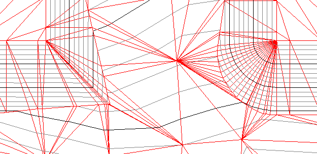
Select Contact: By clicking on the associated button, one has to choose one of the drawing's closed polylines, which the program will take as the platform's crown without considering the slopes' gradient. Its elevation will be displayed in the dialogue box, so it can be edited if necessary unless the polyline has a variable elevation, in which case it cannot be changed.
Should Target Volume be activated, the program will search for a platform elevation around the one proposed by the user at the beginning of the earthwork's calculation. By clicking on the Details button, one can specify the parameters used to search for the elevation.
One indicates in the Drawing box if the program should delete internal points and draw new points at the vertices making up the platform when creating it. The drawing of polylines defining the platform calculated can also be activated.
Result specifies whether the current surface should be modified and applies the changes resulting from earthworks. By default, the program proposes a name for the surface file, so that it does not coincide with any existing files. In addition, you can also specify an additional surface file where you save only the area that corresponds to the earthworks (the completed grading along with its slopes), and a file that represents the earthwork volumes (to be used in the Export to BIM command). By activating the Calculate Volume check box and specifying the Cell Size, the earthworks calculation volume resulting from the grid comparison method is included at the end of the process.
Works Units: This option will be enabled in the event we activate the Earthworks Volume box.
As such, we have the option of assigning works units to both the cut volume and the fill volume calculated after the execution of the platform.
On clicking on the cut or fill button under "Select", the following window will appear in which to assign a main works unit and the different secondary works units.
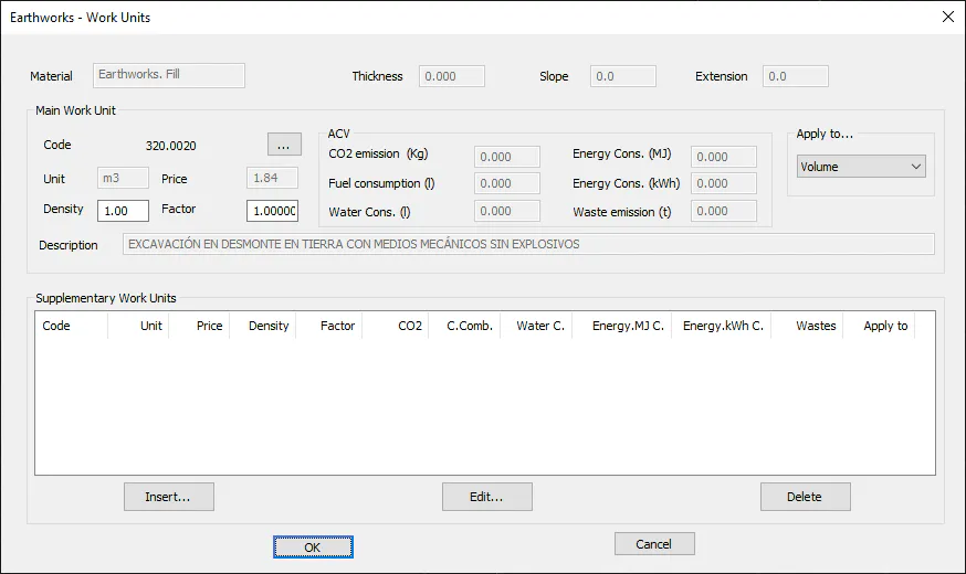
The management of this dialogue box is described in greater detail in the definition of Pavement Layers in the Type Section.
Once the works units have been assigned, we can use the commands available under the Measurements > Works Units command to generate the different reports.
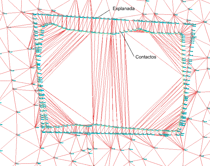
Example of a platform by terrain elevation
Target Volume
The Earthworks by Platform Elevation and Earthworks by Terrain Elevation commands allow one to either enter a proposed elevation or make the program search for the platform elevation to achieve a specific volume of earthworks.
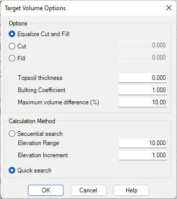
The most common option is to activate the Equalize Cut and Fill option to get the earthworks to equalize the volumes in the cutting and fill areas within a margin. The other two options allow one to search for a specific volume, so that the volume difference between both volumes is a specific Cut or Fill.
The Bulking Coefficient is multiplied by the cutting volume before comparing it with the fill volume. The default value is 1.0 and ensures that this parameter is not considered.
Maximum Volume Difference sets the tolerance margin to compare volumes. If the percentage represented by the difference between the cutting and fill volumes with regard to the total volume is less than this parameter, the program concludes the search and assumes both volumes are equal.
In the section Method of Calculation, a choice between a Sequential Search around the platform elevation entered by the user and Fast Search to try and shorten the searching process is given.
Slopes
The earthworks commands allow different slopes to be used along the polyline that delimits the platform. The Slopes section introduces the cut and fill slope value which will be used throughout the grading. By pressing the corresponding button "..." a window like the following is accessed:
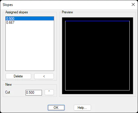
Under New a new slope value van be entered and by pressing the \^ button, the value is added to the list. The window disappears and by pressing the CAD window, points near the polyline of the platform, its programs the slope to the polyline segment where the points entered are projected.
On the Assigned Slopes list each of the values can be selected and under Preview the polyline drawing can be viewed and the segments which have a value assigned are in blue whilst the rest is in white. By pressing the mouse over the preview, the slope of each segment can be changed. Using the Delete button, the value selected from the list is eliminated.
By pressing the "<" button the slope of each segment can also be changed, but by graphically selecting a nearby point on the CAD window. This option may prove more convenient in the event that the preview is confusing. On the command line there is the possibility of designating a continuous interval for polyline segments, entering three points.
Rounding Off Corners
The earthworks\' commands it can be generally specified for all convex vertices whether the slope of the equipment rounds off or not using the option Round Corners. On the right of this option, by pressing the "..." button a window is accessed where each of the polyline vertices of the platform can be configured individually.
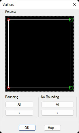
In the preview a circle or a square appears at each vertex depending on whether the slope is rounded off or not at this vertex. By pressing the mouse near a vertex, its behavior is switched. In each Rounding and No Rounding box, All button allow all the vertices to be changed at the same time and using the graphic designation button "<" the vertices can be selected at the CAD window in the event that the preview is confused. On the command line the latter option affords the possibility of designating a continuous interval for polyline vertices, entering three points.
Irrespective of the way in which the program is configured, if the segments before and after a convex vertex have a different slope, the slope is not rounded off.
Related videos
