
tcpMDT
[PRO] Define Vertical Alignment - MDT26

Define Vertical Alignment
 | Command to execute in the CAD |
|---|---|
Vertical menu | MDT26 > Vertical Alignments > Define Vertical Alignment |
Ribbon menu | V.Alignments > Create > Create |
Command line |
Before selecting this command, the current drawing has to have the reference long section represented continuously, that is to say without it being divided into sheets.
First of all, the program will request what type of vertical alignment we are going to work with, or in other words, if the vertical alignment is of the parabolic or circular type.
The program requests the long section's terrain from which the vertical alignment is designed.
The command line then indicates the different ways of defining the vertical alignment:
Graphic
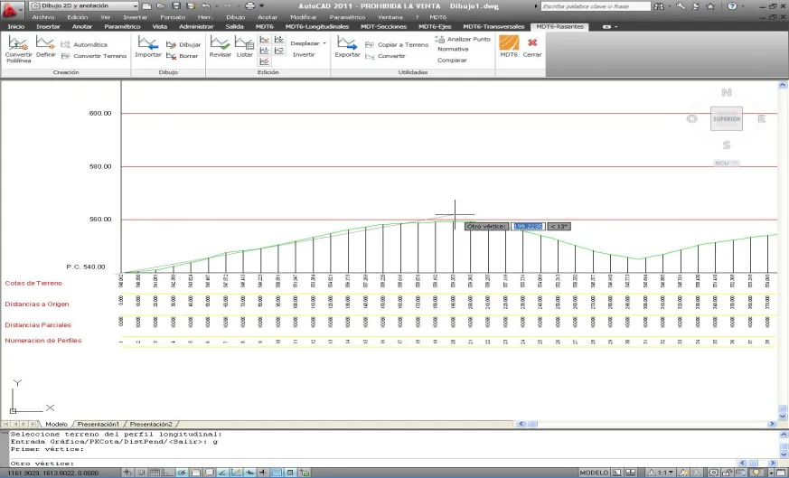
Allows one to define the vertices of the alignments graphically by marking them as if they were the representation of a polyline within or outside the orthogonal projection of the long section's terrain. The definition is completed by pressing twice, so that the program associates the graphic created on the terrain.
Only the areas between the origin and the end of the profile will be drawn. Intersections are calculated and the horizontal alignment outside the area is eliminated, automatically modifying the alignments to leave only the resulting alignment. One can then proceed to export the vertical alignment to a file, so that it can subsequently be used in other processes.
Station and Elevation
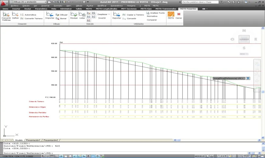
This procedure is similar, but in this case the data is entered in response to the Initial/Final/Reference/ sub-menu. After entering a distance or station, the program requests the elevation and displays the elevation of the terrain interpolated at said position by default.
The Initial and Final options can be used to define the ends of the terrain. Additionally, the Reference option provides facilitates designating a specific point graphically. As explained in the Graphic option, this process may be continuous or partial.
Distance and Slope
This other kind of definition initially displays the same sub-menu as the Station and Elevation option. Once the first item of data (station) is entered, the program requests the elevation and then displays the terrain's data at the point desired by default. After the first point is thus specified, it requests the Distance from the alignment from the first to the current vertex. When this distance is entered, the program requests its Slope. It then creates the new alignment vector based on the previous one and with the distance set. The program will continue to request distance and slope until it is given a null response. Once the vertical alignment has been defined, the program assumes the alignments and matches them to the parameters of the profile's orthogonal projection.
It should be remembered that for a distance of less than zero, the slope to be set in the opposite direction to the left and right, implies a change of sign after the slopes (+ Ramp, - Slope). In other words, for distances of less than zero, both a ramp seen from the final point as well as a slope seen from the final point will have to be considered.
Having described the three procedures for defining straight line segments in vertical alignments, we should mention that they can be alternatively defined using the three methods, accessing each of them without finally completing the process. Lastly, it is convenient to save the alignments' status in a separate file using the Export Vertical alignment option although one may later proceed to the process of matching the vertices.