tcpMDT
Check Long Section - MDT26
Check Long Section
 | Command to execute in the CAD |
|---|---|
Vertical menu | MDT26 > Profiles > Check Long Section |
Ribbon menu | L.Sections > Edit > Check |
Command line |
This application allows us to edit a terrain's long section (lon files) and also works with points long sections (lns) which we can use to extract a terrain's profile from the points and make precise adjustments with the tools provided by the application.
Once we run the application, we'll see something similar to this:
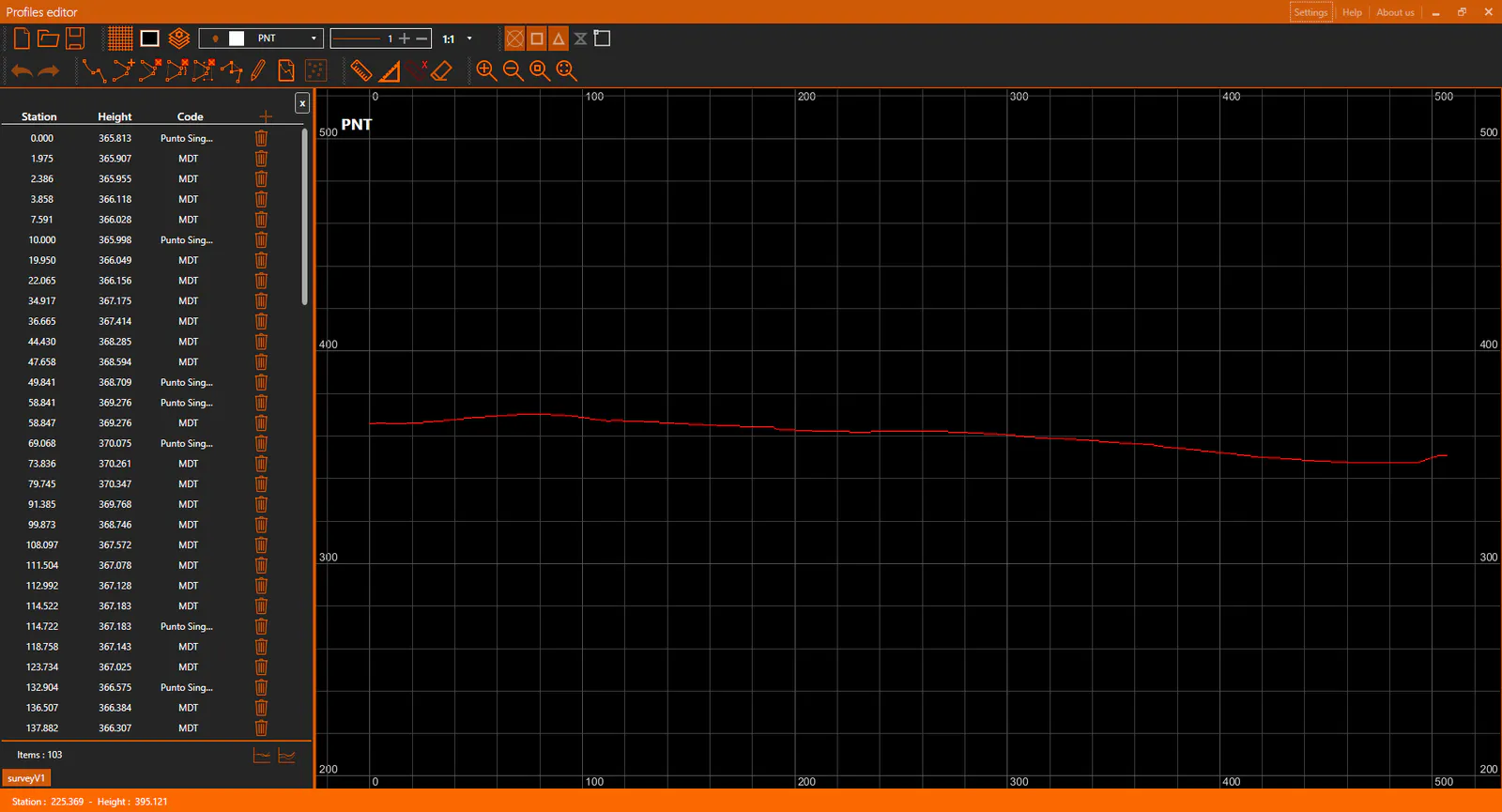
Along this document we are going to detail each of the parts, as a general overview we can distinguish multiple sections in the application's interface:
Title bar: At the top, the orange bar. The application's title appears at the left side. To the right we can find some options: Settings, Help and About us. Further to the right we have the usual window's controls: minimize, maximize/restore and close.
Toolbar: Just under the title bar. It allows us to manage the state of the view and to access to all the different edition tools.
Long sections panel: Under the toolbar, to the left we can see a panel with the information of the current active long section. It is possible to edit multiple profiles, in which case this panel will always show the information of the active one.
CAD View: The application provides a CAD view in which the profiles will be represented as polylines, it also allows us to draw custom polylines and take measures.
Status bar: At the window's bottom, the orange bar. It provides general information like the cursor coordinates in the drawing and information messages during the edition commands.
Settings
At the window's top right corner, we'll find a Settings button. When it's clicked the following dialog will show:
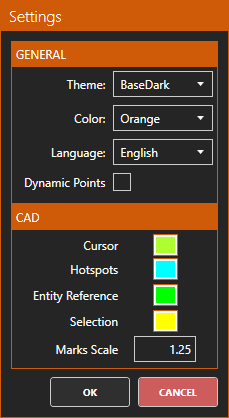
General
Theme: Defines the application's visuals. By default, it's settled as BaseDark so the application should have dark background and light foreground. The alternative would be the BaseLight theme which inverts the previous color scheme: light background and dark foreground.
Color: Defines the color palette used by the application. By default, it's settled to Orange. It can be stablished from a variety of colors.
Language: Allow us to choose the application's language
Dynamic Points: When this option is enabled, the profiles data grids will display the information of the vertices that are visible in the CAD view. If the information of all the vertices doesn't fit in the actual screen size, some intermediate vertices will be skipped. This option could be useful when we need to make a very localized adjustment, because it reduces the visual overload.
CAD
Cursor: Sets the color of the CAD view's cursor. This cursor it's only visible when there's an edition command active.
Hotspots: Sets the hotspots color for the selected entities in the CAD view.
Entity Reference: Sets the color for the entity reference marks in the CAD view when it's doing an operation which uses those references.
Selection: Sets the color for the selected vertices in a CAD view's entity.
Marks Scale: Sets the size scale for the CAD view's marks hotspots and entity references.
Once the dialog is accepted, the current settings will be stablished for current and future program's executions.
Toolbar
In the toolbar we find all the controls that allow us to manage the CAD view and the profiles edition:

File Menu
With the file menu's controls we can create new long sections, add existing files or save the changes of the profiles in edition:
 New: Creates a new longitudinal. It will ask for a file path for the new longitudinal and it will add a blank longitudinal to the panel.
 Open: Asks for a lon or lns file and adds it to the panel and the CAD view. It's possible to work with multiple lon files but there can only be one points longitudinal file (lns) loaded
 Save: If there's an active profile, by default it will ask for a path to store a new lon file with the actual data of the profile: if it has been modified those modifications will be stored, otherwise the file will be an exact copy from the original. If the output's file extension is changed, or there's no active profile when the button is clicked, the following options will be presented:
Save as dxf: Saves the current drawing in the CAD view in a dxf file. This includes polylines and measures drawn by the user.
Save as jpg: Allow us to store a georeferenced screenshot of what is currently visible in the CAD view. To adjust the screenshot settings the following dialog will be shown:
Take Screenshot
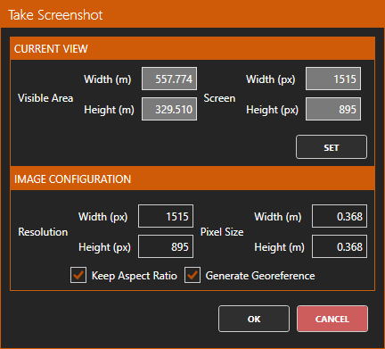
Current View
Visible area: Shows the screen size in meters and pixels.
Set: On click, we enter in a zoom by window command that we can use to set a region in the drawing.
Image Configuration
Resolution: Allow us to set a custom resolution, in pixels, for the screenshot. If the option Keep Aspect Ratio is on, the resolution will maintain the current CAD view's aspect ratio. Varying the resolution will affect the pixel size.
Pixel size: Shows the scale of each pixel in the generated image. For example, for an image which has a visible area of 100x100 meters and a resolution of 100x100 pixels, the pixel size will be 1x1 meters. If the option Keep Aspect Ratio is on, the resolution will maintain the current CAD view's aspect ratio. Varying the pixel size will affect the resolution.
Keep aspect ratio: When it's active the pixel size and resolution are forced to have the same aspect ratio than the CAD view.
Generate Georeference: When active, exports a jpw georefence file along with the jpg image so the screenshot will have the pixel size information and could be drawn or measured on any CAD software that supports georeferenced images. The output image will always be located at the origin X=0,Y=0
CAD Menu
With the CAD menu controls we can manage the CAD view:

 Grid: Enable/Disable the grid
 Background color: Sets the CAD view's background color.
 Layer configuration: Allow us to manage the CAD view's layers. When we click the icon, the following dialog is shown:
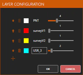
Each layer has the following controls:

 Visibility: Sets if the layer is visible or not.
 Remove: Deletes the layer from the CAD. This is not always possible, there are special layers which can't be removed and whose life cycle is managed by the application. In this case: the PNT layer where the lns files points are drawn and the layers for the long sections in the lon files (one layer per file)
 Layer's name: Allow us to modify the layer's name. There are special layers that can't be renamed. In this case: the PNT layer where the lns files points are drawn and the layers for the long sections in the .lon files (one layer per file)
 Line/Point width: Allow us to set the line/point width for the layer. Is bounded between one and ten.
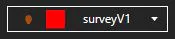
Current Layer: Allow us to select the current layer. If we select a profile's layer (it will have the same name as the file) that profile will become active. Also, layers can be shown or hidden by clicking the visibility icon
 Global line width: Sets the line width for each layer simultaneously.
 Vertical factor: Sets a vertical scale factor to apply to the heights in the CAD view. Allowed factors are: x1, x2, x3, x4, x5 and x10
Entity Reference Menu
With these controls we can manage the CAD view's entity references:
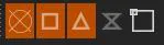
From left to right:
Point reference: When enabled, points are considered in entity referencing. Useful to measure distances between points or drawing on points.
Final Point reference: When enabled, entities vertices are considered in entity referencing.
Middle point reference: When enabled, middle points of linear entities segments are considered in entity referencing.
Near Point reference: When enabled, the nearest vertex to the drawing cursor is considered in entity referencing. Vertex could be final point, middle point or any vertex in a linear entity segment.
Enable/disable references: Sets if entity referencing should be performed or not.
History Menu
With the history menu controls we can undo/redo the changes performed in the profiles:

From left to right:
Undo: Undoes the last change in the active profile.
Redo: Redoes the last undone change in the active profile.
These controls will be active only when there's an active profile with any changes. Each profile has its own independent change history, so it's possible that when the active profile changes one or both controls activate or deactivate.
Edition Menu
With the edition controls we can perform diverse edition commands on CAD view's entities (profiles and drawn polylines)

 Draw polyline: Runs the draw polyline CAD command. If we press the backspace key while drawing, the last inserted vertex will be removed. The command can be finished by pressing Enter or Escape keys.
 Add vertex: Runs the add vertex command. As first step we must select a linear entity to add the vertex to. In case of drawn polylines, the vertex will be added in the nearest segment to the cursor at the moment of selecting the entity. In case of long sections, the vertex will be added at the cursor's coordinates, setting the previous and next vertices according to the X projection of the new vertex (given that in a long section the Station is always growing and can't have two heights at the same Station)
 Remove vertex: Runs the remove vertex command. As first step we must select a linear entity. After that, the entity's vertices will be shown as hotspots and, if we click one of them, the vertex will be removed.
 Remove vertices range: Runs the remove vertices range command. As first step we must select a linear entity. After that, the entity's vertices will be shown as hotspots. We have to click two vertices, the first and last, both will be removed along with all the vertices between them.
 Remove vertices in window: Runs the remove vertices in window command. As first step we must select a linear entity. After that, the entity's vertices will be shown as hotspots. We have to set the two corners of the window, all the vertices contained within the window will be removed.
 Merge polylines: Runs the merge polylines command. As first step we must select the polyline that we want to modify with the merging. After that, we must select the polyline to merge with. Once both polylines are selected, they will be merged according to two criteria: if they intersect, between the first and last intersection points all the original polyline's vertices will be removed and the merge polyline's vertices will be added. Otherwise, the original polyline's vertices closest to the extremes of the merge polyline will be found and the merge will be done in that range. Once the command finishes, the merge polyline is removed.
 Quick edit: It's a shortcut to first run the commands: draw polyline and then merge polylines. If we run the quick edit command, we'll first enter the draw polyline command. Once the polyline is confirmed, the merge polyline command will run automatically, selecting as merge polyline the polyline that we just drawn. This command won't end by itself; it should be finished by pressing Enter or Escape, or with the analogous functions in the context menu.
 Convert polyline: Converts a regular polyline from the drawing into a long section. We'll just have to select the polyline to convert and then the new lon file's path will be requested. The new file will be automatically added to the application for edition.
 Discard points by window: Once we extract a profile from points automatically, this command will be enabled when the extracted profile is active. This command allows us to set a window and then all the points contained in the window will be discarded from the profile extraction process, so the profile will be recalculated in the affected range and the polyline will readapt.
Measuring and Removal Menu
With these controls we can add measures to the drawing, remove them and remove entities from the drawing:
 Measure: The measure command will ask for two points and it will tell the distance between them. A new line will be added to the drawing, along with a text with the line's length, to a special measures layer.
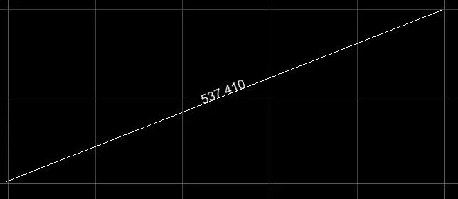
 Measure (XY): It's the same as the measure command except that once the command finishes two additional lines with text will be added showing the distance in the X and Y axis between the two selected points.
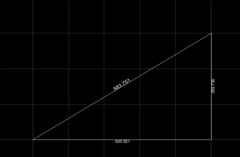
 Remove measures: Removes all the measures from the drawing.
 Erase entities: It allow us to select entities and remove them from the drawing. Once we run this command, when an entity is selected, we'll see that it's lines will become dotted, that means that it's selected for removal. Once all the desired entities are selected, by pressing Enter, or using the analogous function in the context menu, the removal is confirmed. Entities can also be removed by selecting them in the CAD view (clicking on them) and pressing the delete key. There are special entities that can't be removed, as the polylines that represent the long sections.
Zoom Menu
With these controls we control the CAD view zoom level:

Zoom in: Increases the current zoom level.
 Zoom out: Reduces the current zoom level.
 Zoom window: After selecting two points, to set a window, the content of the window will become the current view by stablishing the required zoom level and centering the view at the window center.
 Zoom extents: Fit all the drawing entities on the screen.
Point Management Menu
These controls are only shown when there's a points file (lns) active:
 Extract profile: Allow us to generate a long section automatically from a set of points. The profile will always start at the point with minimum station and elevation. The profile will advance according to the criteria defined in the following dialog:
Extract Profile from Points
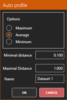
Options: The criteria that must be followed to get the next profile's vertex:
Maximum: Takes the point with the maximum height within the band width defined by minimal and maximal distance parameters.
Average: Takes the average of the points within the band width defined by minimal and maximal distance parameters.
Minimum: Takes the point with the minimum height within the band width defined by minimal and maximal distance parameters.
Minimal distance: From the current vertex to which minimum distance (stations difference) should the next point to consider be at.
Maximal distance: From the current vertex to which maximum distance (stations difference) can the next point to consider be at.
Name: The name for the resulting lon file once the extraction is finished.
 Points size: It allow us to set the size for the points in the CAD view. Can be set between 1 and 10, both included.
 Remove points: Removes the current points profile from the application.
Long Sections Panel
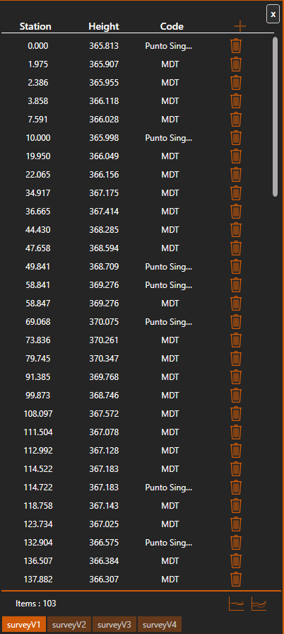
On the left side of the screen, the data from the current in edition profiles will be shown. Additionally, certain operations over the profiles could be accessed from this panel.
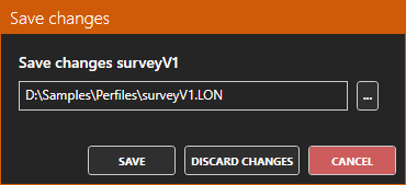
 Close: With this button the active profile will be closed. If this profile had any changes, a dialog will be shown asking us if we want to: store the changes in the original file or a new one, discard all the changes or cancel closure.
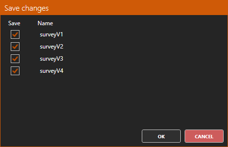
When the application closes, all profiles must close. The following dialog will be shown to confirm the saving of the changes done to the listed profiles (modifying the original files), we could also cancel closure.
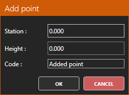
 Add: With this button we can add new vertices to the longitudinal, setting the new vertex's: Station, Height and Code.
Vertices list:
For each profile's vertex, we'll have a line in the list like this one:

The items, from left to right, are:
Station: The vertex's Station. We can double click it to write a new Station for the vertex. The list will be reordered by station after the change. If we attempt to set two vertices at the same Station, the application will show an error message and no changes will be performed, because a long section does not support definition of two heights at the same station.
Height: The vertex's height. We can double click it to write a new height for the vertex.
Code: The vertex's code. We can double click it to write a new code for the vertex.
- Remove: Removes the vertex. It's also possible to remove the vertex by selecting the list's row and pressing the delete key.
If a list row is selected, the vertex will be highlighted on the CAD view.
If we enable the Dynamic Points option in the application's Settings, the list will only show the vertices visible in the CAD view.
Long section's tools:
At the bottom right side of the panel, we can find specific long sections edition tools:

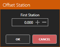
 Offset Stations: It allow us to set a new start station for the long section, modifying, in consequence, all the stations in all the vertices.
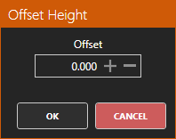
 Offset heights: It allow us to set a displacement to apply to all the heights in the long section.
In edition profiles:
At the bottom of the panel we can see the name of the profiles that are currently in edition:

The highlighted one is the active profile. We can set a profile as active: by clicking its name in the panel, by clicking the profile's polyline in the CAD view, stablishing its layer (the layer with the name of the profile) as the current layer.
CAD View
From the CAD view we can edit the long sections graphically, and also draw and edit polylines:
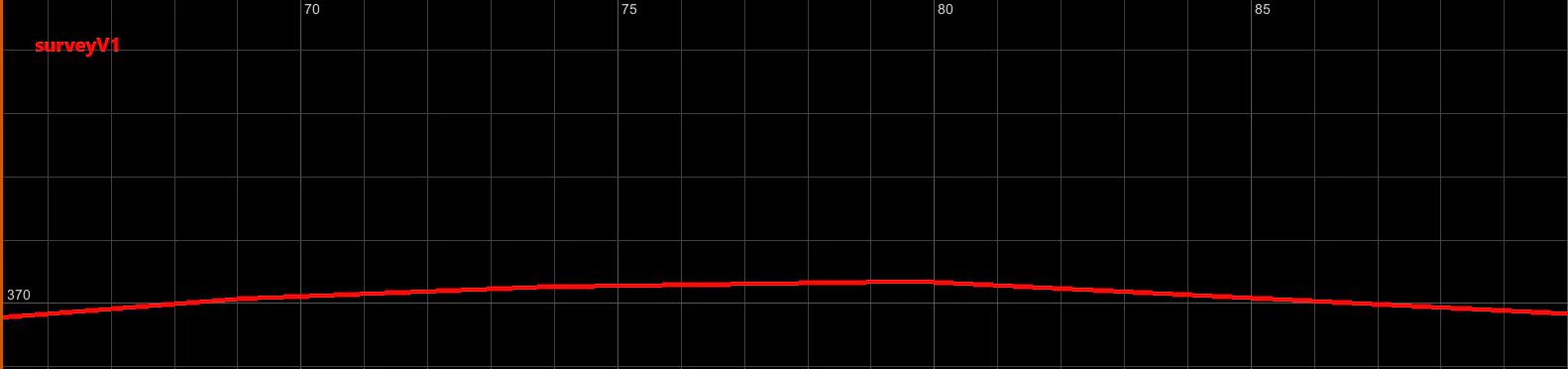
When a polyline is clicked it will be selected and, if it represents a long section, the profile will be set as active. Once an entity is selected, we'll see all of its vertices as hotspots.
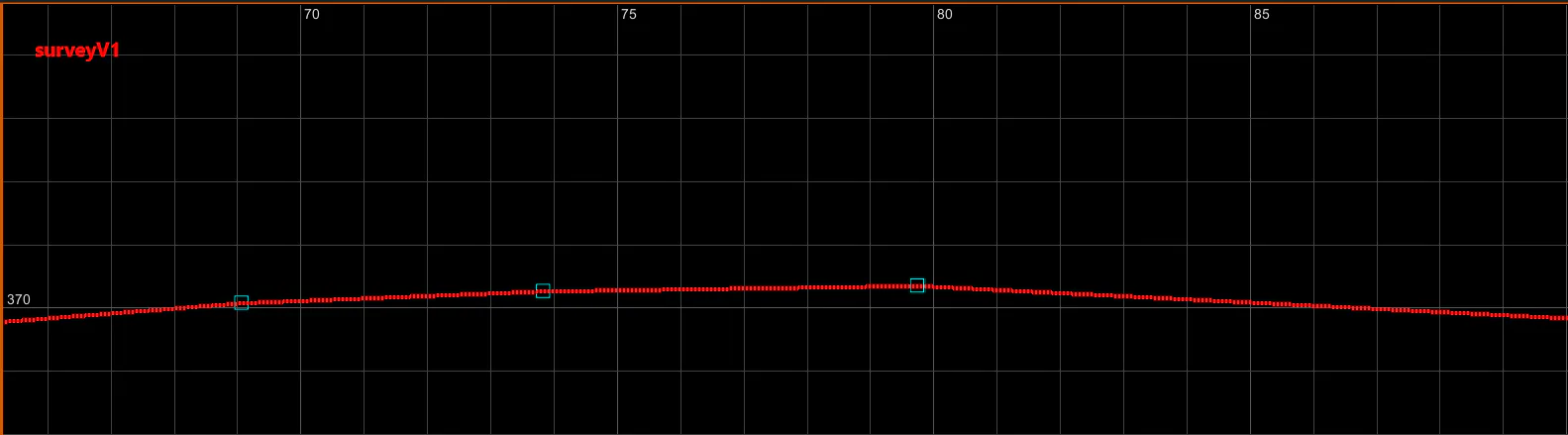
Once in selection mode, if we move the cursor over any of the vertices it will be highlighted in the CAD view and in the panel (in the case of long sections) and the radial context menu will be shown.
Radial Context Menu
When a vertex from a CAD view selected entity is highlighted, this menu will be shown with the possible operations on this vertex:
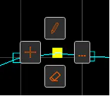
 Edit: It allow us to move the vertex graphically with the cursor. In case of long sections, the edition will force us to keep the vertex's station between the previous and next one.
 Add: Inserts a new vertex. In case of long sections, the insertion has no restrictions. As we move the cursor, we'll see the result of inserting a new vertex at that location. Once we click, the vertex will be added. We can repeat this process as many times as we want, the command will finish when the Enter or Escape keys, or the analogous context menu functions, are pressed. In case of drawn polylines, the new vertex will be added between the highlighted vertex and the next, it's final location will be defined with the cursor.
 Remove: Removes the vertex. It can also be removed, once it's highlighted, by pressing the delete key.
 More options: It will show the context menu with all of the entity's possible edition options.
Context Menu
Any time that we right click on the CAD view, the application's context menu will be shown:
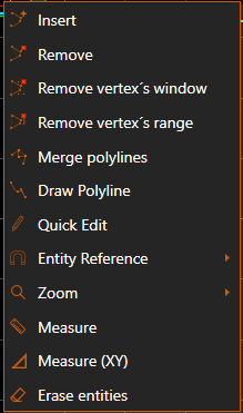
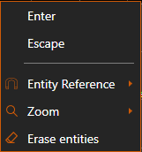
The edition operations will only appear when we right click over an entity. These edition operations are the same than the ones on the Edition Menu from the toolbar, if we use them from this menu, we can avoid selecting the entity when the command runs, because the target entity is already known.
In a similar manner, in the Entity Reference and Zoom submenus we'll find the commands from the menus with the same name from the toolbar:
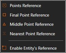
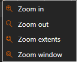
If the application it's in an interactive command and the context menu is opened, by right clicking on the CAD view, additional options will be shown for finishing the command, by Enter or Escape.