tcpMDT
Project Points to Plan View - MDT26
Project Points to Plan View
 | Command to execute in the CAD |
|---|---|
Vertical menu | MDT26 > Profiles > Drawing > Project Points to Plan View |
Ribbon menu | |
Command line |
This command will enable us to ascertain the situation of given points with regard to the alignment on the ground plan of a series of designated points on the long section. The purpose of this option is to have the possibility of marking on the mapping from which the long section has been generated a series of designated points on the long section drawn beforehand.
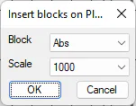
With this in mind, the command will initially ask us to designate the long section drawn and the alignment from which it was generated. The following window will then appear in which we will select the block to be inserted as well as the drawing scale.
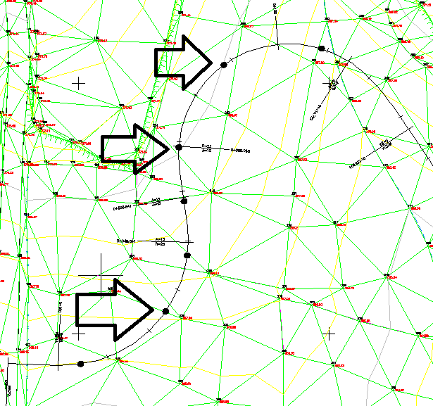
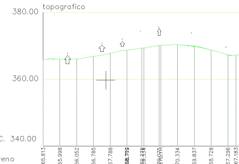
Once the window has been validated, we will designate the points on the profile and simultaneously the selected block will be drawn in its position in accordance with the designated alignment. In addition, a circle will be drawn on the profile at each of the designated points on it.
 |  |
|---|---|
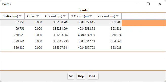
Once the points designation is complete, a list will appear with information from all the points calculated with the possibility of printing them.
Project Profile to Plan View
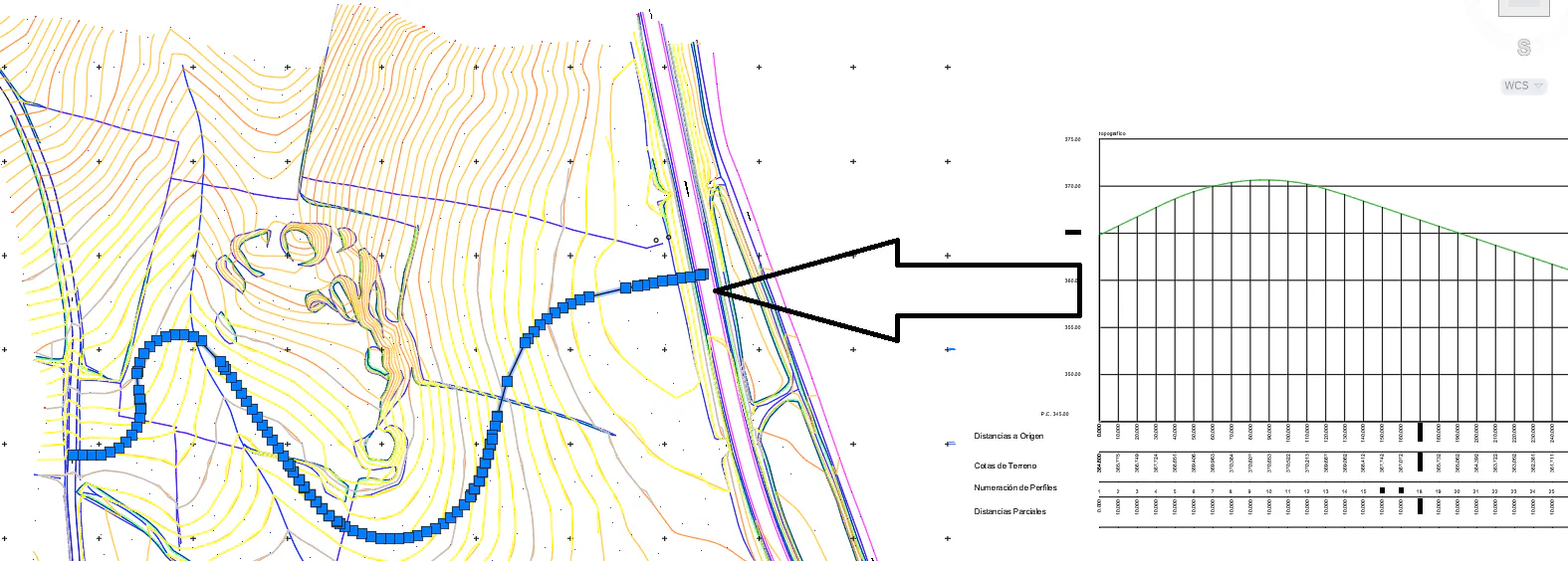
This option will allow us to project a long section to the plan view. A 3d polyline will be created, with as many vertices as vertices have the long section and with its elevations.
Initially, it will request that the drawn long section or the long section file be designated, and then designate the corresponding alignment or file.
Finally, the commented 3d polyline will be drawn.
Draw Section in Long Section
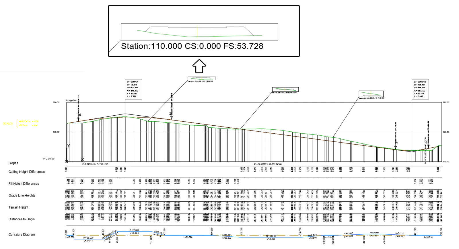
This command enables us to include in the previously drawn longitudinal the finished template in the stations designed graphically by the user. The profile or template of the station nearest to that selected on which information exists will be drawn.
To do so, we first need to draw the profile with the vertical alignment by executing the Draw Compound Profile command.
Once the profile has been drawn, we execute the command, firstly we will be asked to select the long section and the following window will appear for the configuration of the elements to be drawn.
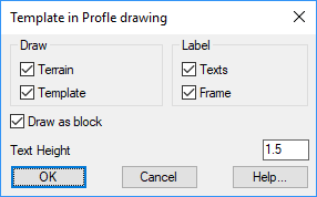
Draw Terrain: Activating this box will draw the natural terrain of the station selected.
Draw Template: Activating this box will draw the template of the station selected.
Label Texts: Will label the station and the surfaces of the station.
Frame: A frame will be created in the profile drawing.
Draw as block: Activating this box will insert the drawing as a block, which will facilitate changing the insertion point of the same.
Text height: The height of the texts when activating the Label Texts box.
Once the dialogue has been validated, the command will ask us repeatedly for the vertices on the longitudinal on which we wish to calculate and draw the template type.