
tcpMDT
List Long Section - MDT26
List Long Section
 | Command to execute in the CAD |
|---|---|
Vertical menu | MDT26 > Profiles > List Long Section |
Ribbon menu | L.Sections > Edit > List |
Command line |
When this command is executed, MDT asks requests a file with the .LON and .SEG extensions. Initially, a previously drawn long section can be selected graphically. The result of the list will depend on the type of file selected. Both types are described below.
Long Section List
Once the file has been selected or the profile graphically selected, the following list divided into five columns is displayed: Distance, *Elevation, Partial distance, Slope and Code*.
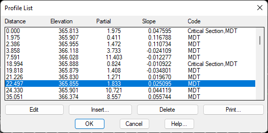
This window contains a series of buttons which allow one to modify the long section's data.
Edit: Allows the height or code of the station selected to be modified. The following window is displayed in order to do so. In it the values of the vertex selected will appear by default. Once this dialog box has been validated, MDT will update the list, sorting the cuts by their distance from the origin.
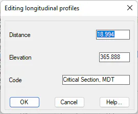
Insert: Allows one to insert new characteristic points on the long section. When the button is clicked, the following window is displayed, where the information on the new node desired can be entered. When the dialog box is validated, MDT will automatically sort the list.
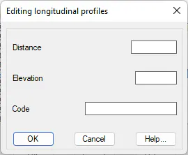
Delete: Deletes the vertex selected.
Print: Allows the list to be printed on hard copy or sent to a text file.
Once the dialog box has been validated, the changes are saved in the file selected previously. If a profile has been graphically designated, its drawing will be updated.
Segment List
Once a segment file has been selected, the program displays the following window:
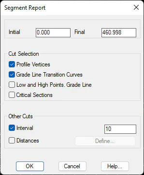
This dialog box configures the type of list one wishes to obtain. Each of the controls making it up are described below.
Initial and *Final Station: The station interval one wishes to obtain is set here. First the initial and final stations of the long section comprising the segment are assigned (see definition of Segment in the Horizontal Alignments* section).
Cuts Selection The characteristic points of the long section, the grade line or the horizontal alignment one wishes to list are selected.
Profile Vertices: All the vertices comprising the profile are listed.
Grade Line Transition Curves: The grade line's transition curves are listed, in other words, the entry and exit tangents, as well as the vertex.
Low and High points, Grade Line: A list is provided of the stations featuring the maximum and minimum elevations on the vertical alignment curves.
Unique Points: The characteristic points of the horizontal alignment the segment selected contains are listed.
Other Cuts: In this section, other cuts are entered that the user may be interested in seeing on the list.
Interval: Depending on the value entered, MDT will represent the long section's cuts using this value as an interval. The cut height will be interpolated between the previous and next vertices.
Distances: If this button is activated, a dialog box will be displayed, where the specific distances one wishes to list are entered. They can either be typed in with the keyboard or selected graphically. The dialog box displayed when this button is clicked appears below.
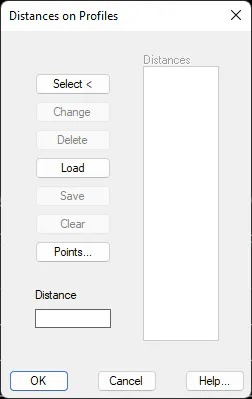
Once the main dialog box has been validated, the following list appears. It shows the characteristics listed below for each cut.
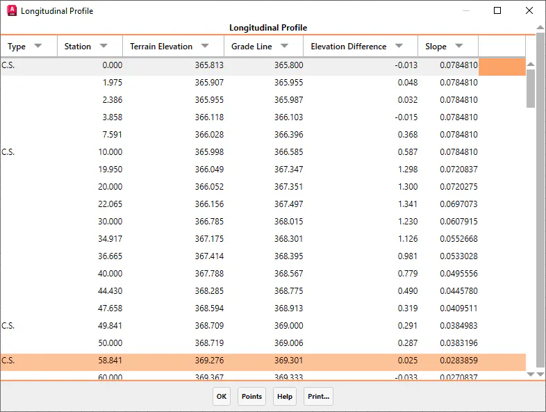
Type: Indicates the characteristics of the cut or interval's:
C.S.: Horizontal alignment's critical section
V.: Grade line transition curve's vertex.
I.T.: Grade line's input tangent.
O.T.: Grade line's output tangent.
Station: Indicates the long section's distance to origin.
Terrain Elevation: Represents the terrain's elevation.
Grade line Z: Represents the grade line's elevation.
Elevation Difference: Represents the elevation difference between the terrain and the grade line, with a sign.
Slope: Represents the grade line's slope.
The following additional buttons also exist:
Print: Sends the list to the Windows default printer.
Excel: Sends the information to an Excel spreadsheet.