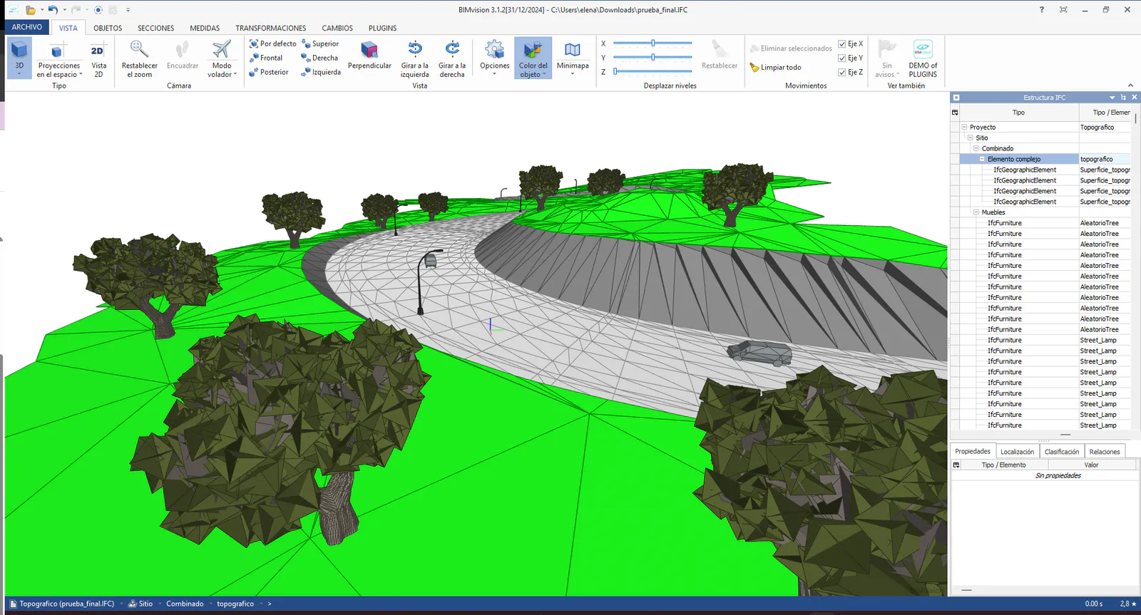
tcpMDT
Export IFC - MDT26
 | Command to execute in the CAD |
|---|---|
Vertical menu | MDT26 > BIM > Export IFC |
Ribbon menu | BIM > BIM > Export IFC |
Command line |
Export IFC
With this command, we will export the content of our project to an IFC file. When executing the command, the first of four windows will initially appear, as part of a wizard where all the necessary data for the IFC export will be requested.
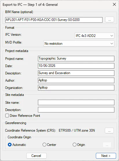
BIM Name
This allows us to give our exported IFC file a name according to the BIM Nomenclature. To do this, we press the button with the three dots, which shows us the corresponding dialog to select, in each case, the option that best fits our work and its status.
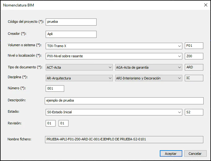
On the website https://www.buildingsmart.es/recursos/nomenclatura-documentos-bim/, we can download a manual about BIM Nomenclature.
General Data
We detail the characteristics of the project, such as name, company, location... All the fields described below are optional and specifying them is not mandatory for generating the IFC file.
Each of the characteristics is described below.
Format: We indicate the IFC Version and the MVD Profile.
IFC has different versions of the format; currently MDT supports the following versions:
IFC 2X3
IFC 4
IFC 4X1 (Deprecated)
IFC 4X3
Project Metadata:
Name: Project name, it is the same value as in the main IFC import window.
Phase: The current state of the project.
Description: A description of the project's characteristics.
Author: Details of the project author.
Organization: Details of the organization to which the project belongs.
Site Metadata:
Site Name: Description of the location where the project is carried out.
Description: Additional information related to the location where the project is carried out.
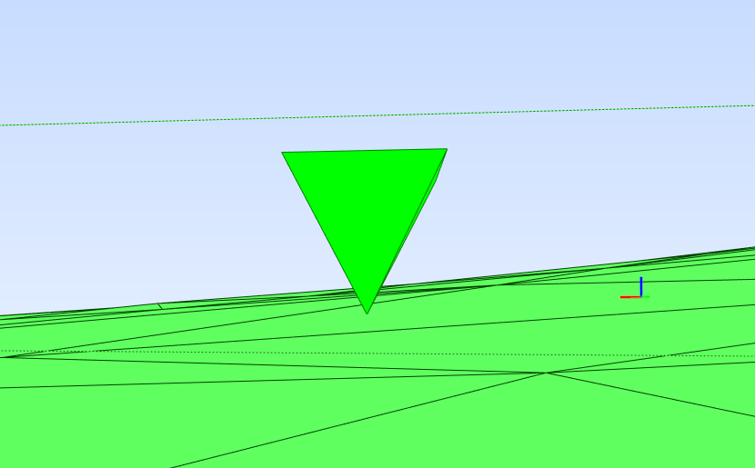
Draw Reference Point: If we activate this option, a pyramid will be drawn marking the selected reference point in the Coordinate Origin.
Georeferencing:
Coordinate Reference System (CRS): Reference system in which the project to be exported is located.
Coordinate Origin: For the project to be exported, we can configure its coordinate origin.
Automatic: By default, the coordinates of the project itself.
Center: The center of the surface to be exported is set as the reference coordinates.
Origin: Selection of specific coordinates in the drawing.
The next step of the wizard shows us the objects that will be exported:
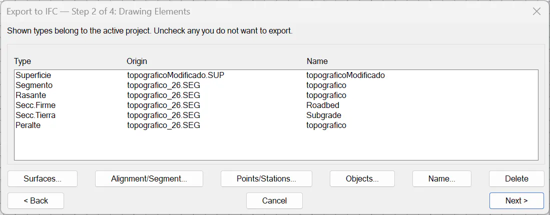
Surface: Allows selecting Surface files (.sup) or Earth Movement files (.mt). Allows selecting multiple files.
Axis/Segment: Allows selecting Axis files (.eje) or Segment files (.seg). If a segment is selected and it has defined pavement layers, these pavement layers will also be exported to the IFC format along with the segment's alignment.
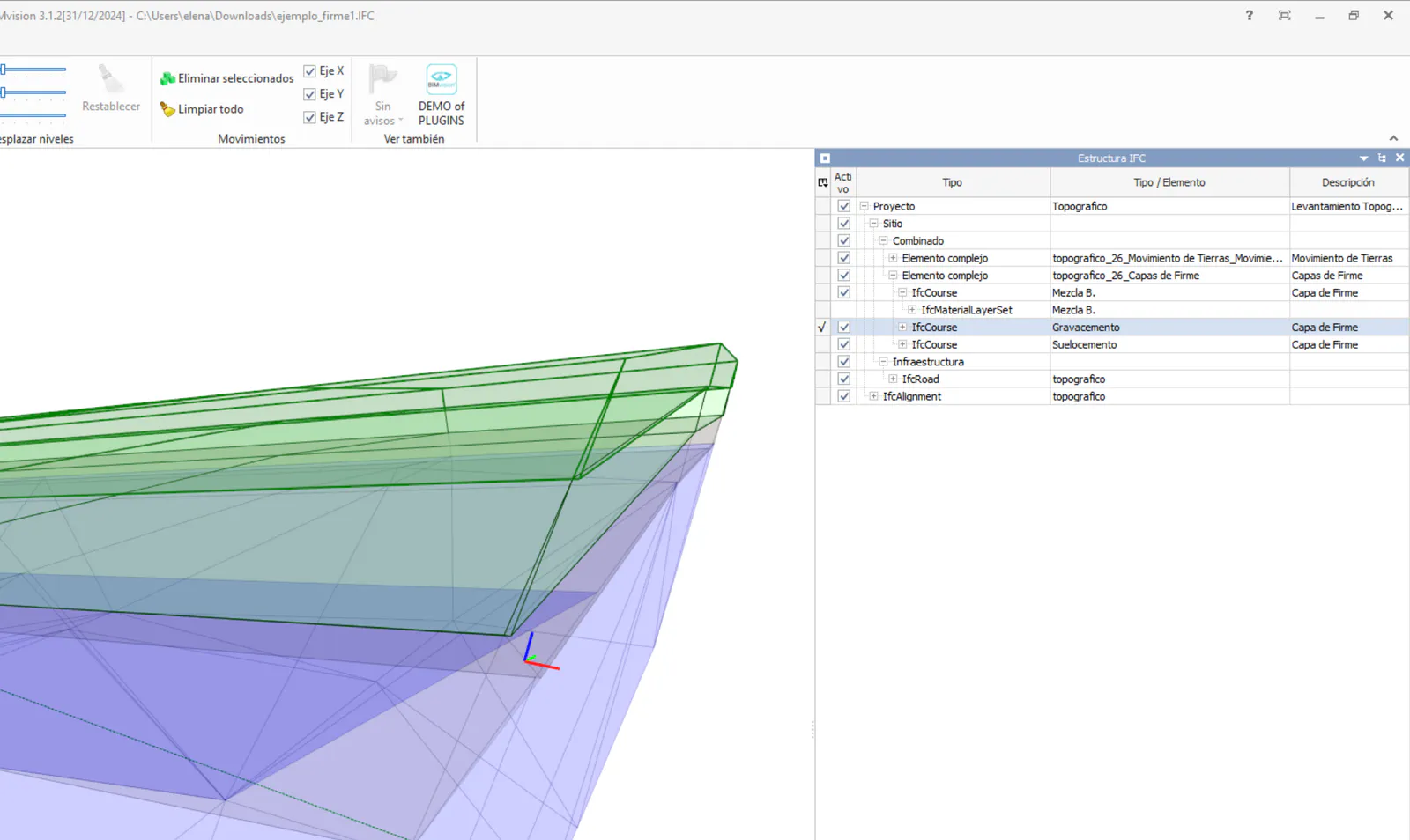
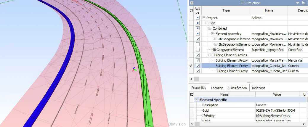
In the event that the gutter of our section has a lining thickness, it will be modeled by applying a texture for its visualization. In the following image, a definition of gutters on both sides of the axis can be seen.
Points/Bases: Allows selecting files of type Points (.pun) or Bases (.pun). In Utilities > Configuration > BIM, it is possible to customize the shape of the Point or Base to export.
Objects: From this option we have the possibility to export to IFC the outline of closed polylines. For this, the polylines to export must be at the elevation we want to display.
This option is particularly useful if we want to show horizontal signs in our IFC file, for example, pedestrian crossings, direction arrows...
It is managed with the following window:
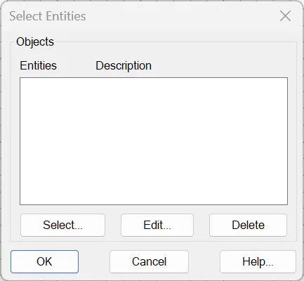
With the buttons "Select", "Edit" and "Delete" we manage the list of objects.
If we press the buttons "Select" or "Edit" the following window will appear from which we will select the objects or polylines to export.
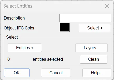
Description: Comment that we want to associate with the selected set of entities or polylines.
IFC Object Color: Color with which the objects will be displayed in the IFC file.
Selection: Selection mode of the entities or polylines
Entities: Graphical selection.
Layers: Selection of polylines contained in one or more layers.
Clear: Deletes the selected entities.
Name: Allows editing the Name of the selected element.
Delete: Allows removing the selected element from the list, or if not, the first element of the list.
MDT has the ability to classify the different objects to be exported. In the third step of the wizard, it shows us a list of classification systems that have been marked as active in the configuration, and allows us to select which will be included in the IFC file and which will not.
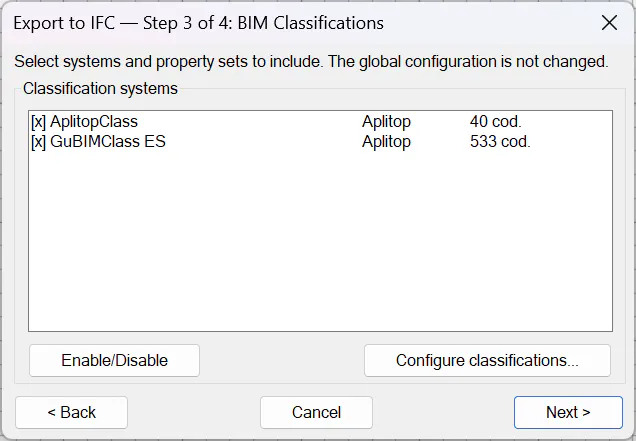
Activate/Deactivate: allows selecting the classifications to be added or not to the IFC file by marking with an X those to be included.
Configure Classifications: accesses the classification systems management dialog in the settings.
These classifications have been generated by different entities and we currently have the possibility to classify according to these standards.
AplitopClass
UniClass 2015
guBIMClass ES
guBIMClass CA
OmniClass
SCFclass
UniFormat II
From Settings > BIM, it is possible to customize these classifications and even add new ones through the two buttons Classification Systems and Object Assignment.
On the last screen of the wizard, we can access the properties and it shows us a summary of the data that will be exported:
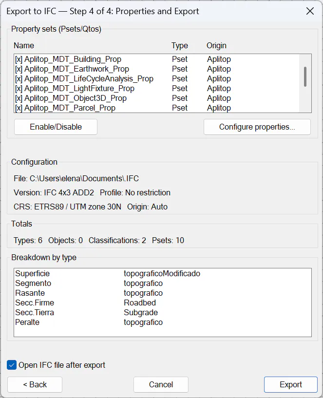
Property Sets: Ability to assign specific properties to the project to be exported. For more details, consult the options BIM > Property Set Definition or BIM > Property Assignment.
Enable/Disable: allows selecting those properties that, being active in the property configuration, will be included in the IFC file.
Configure properties: to access the Property Sets dialog.
Configuration: summary of the most important details in the export and list of objects to export.
If the option Open IFC file after export is checked, the default BIM application will automatically open with the exported IFC file.
Signage
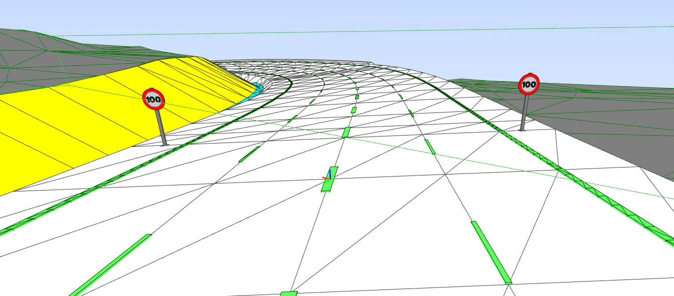
TcpMDT has the capability to export both vertical and horizontal signage to IFC for a specific segment or road.
Horizontal signage or road markings: For this, in the definition of Sections, under the Road Markings section, specify the type of marking for each vector of the section. Once this section is configured, the markings will automatically export to IFC without any additional steps.
Vertical signage: Prior to exporting to IFC, it is necessary to insert the vertical signage into the drawing. To do this, use the option Maps -- Realism > Insert 3D Object. Once the signs are inserted, when executing this option, the IFC export window will automatically display an entry named "Vertical Signage" as an element to export.
3D Objects
TcpMDT also allows the export of objects associated with the blocks inserted in our drawing.
Due to viewer limitations, these objects are represented only by color.
In the IFC file, the 3D objects will appear in the position, with the scale and rotation applied in the drawing.