
tcpMDT
Import IFC - MDT26
 | Command to execute in the CAD |
|---|---|
Vertical menu | MDT26 > BIM > Import IFC |
Ribbon menu | BIM > BIM > Import IFC |
Command line |
Import IFC
When executing the command, it will initially request the IFC file, once selected, the following window will appear in which both the characteristics of the project itself and its contents are displayed.
This option offers us the possibility of importing each of the elements.
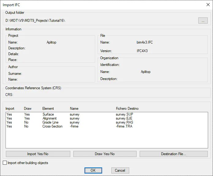
Information: All the information contained in the IFC file and related to the project is shown.
In the list we will see the different elements that the file contains, in this case, it contains a surface, a horizontal and a vertical alignment.
Import Yes/No: We select the element we want to import.
Draw Yes/No: We indicate if after the import, we want the imported element to be drawn automatically.
Destination File: We select the name of the destination file of the element to be imported.
Import other building objects: If we activate this option, the IFC file to be imported will be analyzed and those elements that have their own representation will be imported as 3D Faces of the CAD, regardless of the elements of roads, such as Alignments, Surfaces and Grades.
The following objects are currently processed whether or not they have a 3D representation:
MDT Category | Recognized IFC Entity(ies) | Schema restriction |
|---|---|---|
Surface / Natural terrain | IfcGeographicElement | IFC4x3_ADD2 / IFC4 |
Surface / Natural terrain | IfcBuildingElementProxy | IFC2x3 |
Earthworks (cut/fill) | IfcEarthworksElement | Only IFC4x3_ADD2 / IFC4 (no equivalent in IFC2x3) |
Plan alignment | IfcAlignment | Only IFC4x3_ADD2 or IFC4x1 (no branch for plain IFC4 or IFC2x3) |
Vertical alignment | IfcAlignmentVertical | IFC4x3_ADD2 |
Vertical alignment | IfcAlignment2DVertical / IfcAlignment | IFC4x1 |
Cross-section | (not its own class; extracted from IfcRelNests + IfcShapeRepresentation hanging off the IfcAlignment) | IFC4x3_ADD2 / IFC4 |
Topographic points / Survey bases | IfcAnnotation (distinguished by PredefinedType: SURVEY = base, others = point) | Shared across all schemas |
Vertical sign | IfcSign | Only IFC4x3_ADD2 (does not exist in IFC4/2x3; therefore in those schemas it is exported as IfcFurnishingElement, although the current importer only looks for IfcSign) |
3DObject | IfcFurniture | All |
"Shell" / generic objects (objetosShell) | IfcFooting, IfcColumn, IfcPile, IfcWall, IfcSlab, IfcBuildingElementProxy, IfcConnectedFaceSet (raw shell geometry), IfcSite | No difference by schema |
Networks (manholes/pipes) | IfcFlowFitting (manholes), IfcFlowSegment (segments), IfcSite | Old API (no schema template) |
Parcels/buildings/pools | IfcMapConversion, IfcSpatialZone, IfcBuilding, IfcBuiltElement, IfcBuildingElementProxy | — |
Once the dialog is accepted, the elements will be imported and drawn if applicable.
Additionally, if the element to be imported has properties or classifications assigned, a dialog is shown displaying the properties detected in the file so that the user can decide whether to import them and include them in the application's global configuration; similarly, an equivalent dialog will appear for classifications.
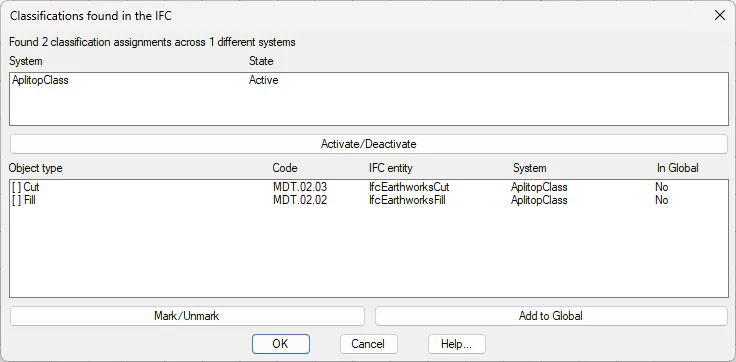
To view the properties assigned to any element (alignment, surface ... ) we have the command BIM > Property Assignment.
And to view the classification code assignments for any MDT object we have the command BIM > MDT object classification.