
tcpMDT
Import LandXML - MDT26
 | Command to execute in the CAD |
|---|---|
Vertical menu | MDT26 > BIM > Import LandXML |
Ribbon menu | BIM > BIM > Import LandXML |
Command line |
Import LandXML
This command converts a LandXML file into MDT files (points, surfaces, alignments, grade lines, superelevations, profiles and cross-sections) and, optionally, creates the segments of the roads it contains. It supports both generic LandXML files and files exported from Civil 3D.
The program first asks for the LandXML file and then displays the Import LandXML file window with the elements found in it.
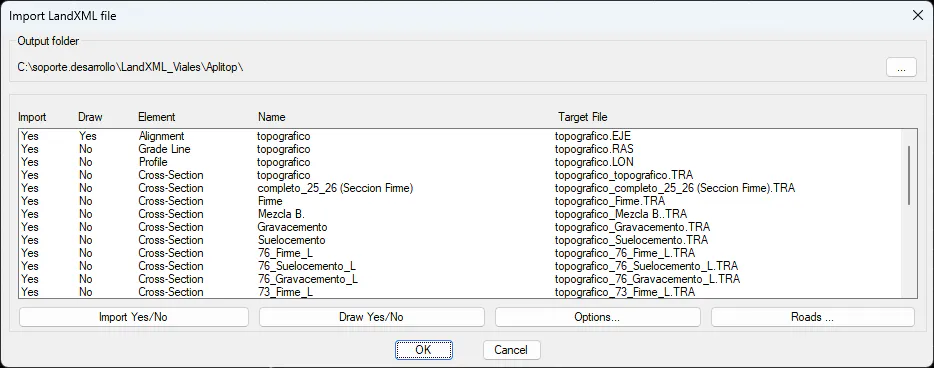
Output folder: folder where the converted files will be created. Each file takes the name of the element and the corresponding extension. The ... button selects another folder; when it is changed, the path of all target files is updated.
Element list: for each element of the LandXML file, it shows the following columns:
Import: Yes/No, indicates whether the file will be generated.
Draw: Yes/No, indicates whether the element will also be drawn.
Element: element type (Points, Surface, Alignment, Grade Line, Superelevation, Profile, Cross-Section, Break Lines, Plots).
Name: name of the element in the LandXML file.
Target File: name of the file that will be generated.
The list allows multiple selection. The buttons act on the selected elements:
Import Yes/No: enables or disables the import.
Draw Yes/No: enables or disables drawing. It only applies to points, surfaces, alignments, break lines and plots; grade lines, profiles and cross-sections are not drawn.
Options...: with a single element selected, allows changing the target file. For surfaces it opens the Import Surface dialog:
Import and File: enable the import and set the target file.
Draw, Layer and color: enable drawing and define the layer and color of the triangles.
Draw Break Lines: also draws the break lines of the surface, if the file contains them.
Roads ...: opens road creation (see below). It is only enabled if the file contains alignments.
If a single surface marked to be drawn is imported and there is no current surface, that surface becomes the current surface when the import finishes.
[!note] Units If no units have been specified in the program configuration (Utilities > Configuration > General), the import does not perform any conversion: the units of the LandXML file are transferred 1:1 to the target files. If units have been specified, the LandXML data is converted to those units. The conversion applies to alignments, grade lines, superelevations and cross-sections (for example, Civil 3D files in feet).
Road Creation
The Roads ... button displays the Alignments List of the file, with the columns Alignment, Generate, Natural Terrain, Grade line and Section, which summarize the choices made for each alignment.
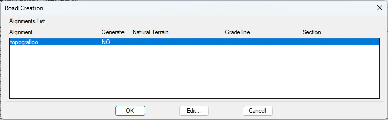
Edit... (or double-click) configures the road of the selected alignment:
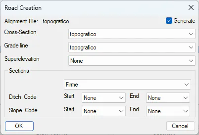
Alignment: name of the alignment. The Generate checkbox indicates whether the segment of that alignment will be created; the remaining controls are only enabled when it is checked.
Cross-Section: cross-section used as the natural terrain of the segment.
Grade line: grade line of the segment. It is also the reference grade line used to import the cross-sections of that alignment (in Civil 3D files, section elevations are relative to the grade line).
Superelevation: superelevation of the segment, chosen from those in the file for that alignment, or None. The first one is proposed by default.
Sections: cross-section from which the typical sections (platforms, ditches and slopes) are generated.
Ditch. Code Start / End: cross-section codes between which the ditch lies.
Slope. Code Start / End: cross-section codes between which the slope lies.
The code lists contain the vertex codes of the cross-section chosen in Sections, plus the None option. By default, the codes from the configuration (Ditch_In for the ditch and Daylight for the slope) are proposed if they exist in the cross-section. If None is chosen as the end code, the ditch or slope is not included in the section.
Cancel in the Alignments List undoes all the changes made in it.
Result
When the import is accepted, a segment (.seg) is created for each alignment with Generate checked. It takes the name of the alignment, is saved in the folder of the LandXML file and is made up of:
The selected alignment and grade line.
The selected natural terrain cross-section.
The selected superelevation. In Civil 3D files, the superelevation (Superelevation) is imported: the crown is MDT's (2%) and the superelevation side is obtained from the turning direction of each curve of the alignment.
The sections (.sec), generated from the cross-section chosen in Sections with the specified ditch and slope codes.
Pavement layers: if the Civil 3D file contains the closed shapes of the pavement layers, they are assigned to each platform vector with their thickness and material (materials are added by name), and pavements are created by station ranges.
Only the elements marked for import in the main list are included in the segment. If the alignment is not imported, its segment is not created.
All generated files are added to the project and listed on the command line.
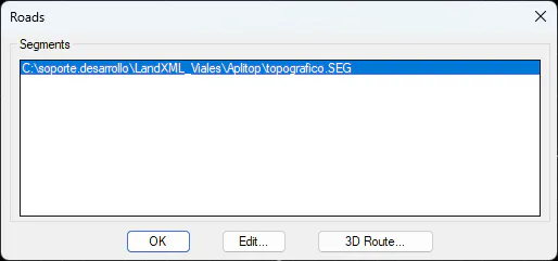
When the process finishes, the Roads dialog is displayed with the list of generated Segments:
Edit... (or double-click): opens the definition of the selected segment.
3D Route...: opens the 3D route of the selected segment.