
tcpMDT
Convert Cross Sections from Drawing - MDT26
Convert Cross-sections from Drawing
 | Command to execute in the CAD |
|---|---|
Vertical menu | MDT26 > Cross-sections > Create Cross-Sections > Convert Cross-Sections from Drawing |
Ribbon menu | X.Sections > Utilities > Convert Drawing |
Command line |
This command is particularly useful to obtain the cross-section file in ASCII format from cross-sections represented on the drawing by polylines representing the profiles. There are three alternatives depending on how the drawing was made.
When the command is executed, the following window is displayed to select the operating mode:
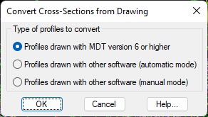
Profiles Drawn with MDT Version 6 or Higher
This option is very useful if the profile drawing has been done with MDT version 6.0 or higher and later on the drawing modifications have been made.
In the case that the drawing is a segment drawing, the command will request the corresponding segment as an output file, saving the changes made to the drawing in the natural terrain cross-sections file. If on the contrary, a cross-section has been modified, it will request the corresponding natural terrain file.
Profiles Drawn with Alternative Software (manual Mode)
In this case the program will request the following data in the command line:
Terrain: Graphically select the terrain we wish to convert.
Station: Introduce the station corresponding to the terrain selected.
Elevation: Introduce the height of the terrain selected.
Horizontal alignment position: Graphically select on-screen the vertex corresponding to the position of the horizontal alignment in the cross-section.
When we finish entering the data, MDT will request the file in which we wish to save the profiles obtained.
Profiles Drawn with Alternative Software (automatic Mode)
If we select this option, the following dialog box will be displayed. A description follows.
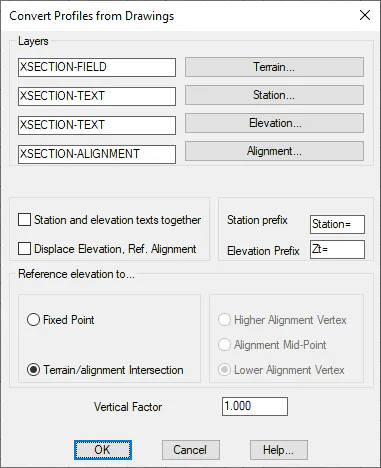
Layers: Select the layers where all the cross-section elements are located, meaning: the natural Terrain, the text of the Station, the text of the Elevation and the line or polyline that represents the Alignment.
Station and elevation texts together: This option must be selected if the station text appears in the same text entity.
Displace Elevation Ref. Alignment: If this option is activated the elevation that is to be associated to the cross-section will be the labelled elevation minus the length of the vertical alignment that corresponds to the cut of the cross-section to convert.
Station prefix.: The text that precedes the number indicating the station of the cross-section cut must be specified. By default, "Station=".
Elevation Prefix.: The text to precede the number that indicates the cross-section cut height. By default, "Zt=".
Reference elevation to: These options indicate how to associate the text of the height of each cross-section cut with the position of the horizontal alignment of the same.
Terrain / alignment intersection: The height assigned to the position of the cross-section alignment is the height of the corresponding text.
Fixed point: In this case the position of the cross-section alignment is assigned the height of the text selected but with a displacement, the behavior of this displacement shall be in accordance with one of the following options.
a. Higher Alignment Vertex: In this case the height read in the drawing corresponds to the highest point of the line representing the horizontal alignment.
b. Alignment Mid-Point: In this case the height read in the drawing corresponds to the midpoint of the line representing the horizontal alignment.
c. Lower Alignment Vertex: In this case the height read in the drawing corresponds to the lowest point of the line representing the horizontal alignment.
Vertical Factor: By default, this is 1, this is the multiplication factor of the elevation difference of the vertices that comprise the cross-section.
Once the dialog box is validated, MDT will request a cross-section file to transfer the data resulting from the conversion.