tcpMDT
Draw Cuts - MDT26
Draw Cuts
 | Command to execute in the CAD |
|---|---|
Vertical menu | MDT26 > Cross-sections > Drawing > Draw Cuts |
Ribbon menu | X.Sections > Drawing > Draw Cuts |
Command line |
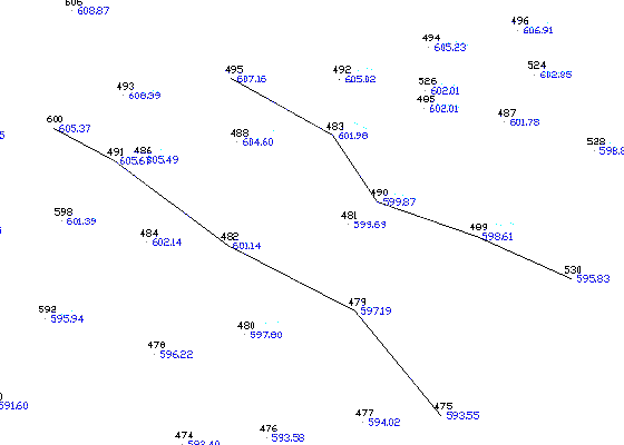
The working of this command is linked to Convert Cross-Sections from Cuts. Its aim is to put together cross-sections by selecting surveying points from left to right and determining the station (either manually or automatically using a constant interval), in addition to positioning the horizontal alignment's point. The selection of these profile components as well as of the horizontal alignment is done by the positioning of the closest point.
The command area of the program requests the Initial Station and the Interval (constant distance between profiles). If the latter is constant, its value is indicated. It is zero if one wishes the program to request it for each station. The selection of points on the same profile is displayed by the creation of a 3D polyline joining the points selected on the XSECTIONS layer.
After joining all the points defining the profiles one by one, the Convert Cross-Sections from Cuts command should be executed, which reads what is represented in the formation.