tcpMDT
Create Skewed Cross Sections - MDT26
Create Skewed Cross-sections
 | Command to execute in the CAD |
|---|---|
Vertical menu | MDT26 > Cross-sections > Create Skewed Cross-Sections |
Ribbon menu | X.Sections > Create > Skewed Profiles |
Command line |
This command is useful to generate profiles that are not normal to the horizontal alignment. It is possible to indicate the angle of inclination with regard to the horizontal alignment of each cut or group of cuts. This angle is specified in grads with a margin of +- 100 degrees, in which the value of zero is considered normal to the horizontal alignment.
The information is saved in the file selected with the extension "TRE", differentiating it from the traditional cross-section profiles as a completely new and independent element.
When the command is executed, the following window is displayed. Its parameters are described below.
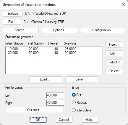
Surface: Select the surface from which to generate the profiles, in the case that it exists.
File: Name of the skew cross-sections file to be generated.
Origin: This option is exactly the same as the same button that exists under the command "Obtain Profiles".
Options
This option, in general, is used to personalize the representation of the profiles in ground plan view.
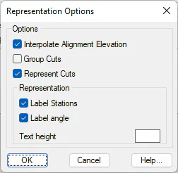
Interpolate Alignment Elevation: If no information exists in the alignment position, the position elevation is interpolated.
Group Cuts: This creates a block with all the cuts represented in ground plan view, to enable the option after all the cuts are deleted.
Represent Cuts: Check this box to represent the cuts in ground plan view.
Label Stations: Used to label the station corresponding to each cut.
Label angle: When this option is checked, the angle corresponding to each cut is labelled.
Text height: To personalize the text height for both the station and the angle.
Stations to Generate
In this section we indicate which cuts to generate, at which stations and what the angles of these will be. There are several groups of cuts or individual cuts, each one with its own angle. There are several ways to input this data:
Insert: A window is displayed to establish the initial station, final station, the interval between the cuts and the angle of this group of profiles.
Edit: Edit the element selected making any modifications to its parameters.
Select: With this option there must be previously drawn lines indicating from where to obtain the cuts in the drawing in ground plan view. By clicking this button, we select each one of these lines and the command to automatically calculate the station and the angle of each one. It is necessary in all cases that the lines cut the horizontal alignment.
Delete: Delete the entry selected in the list.
Read: This option is used to read the information previously recorded with all the information on the cuts to generate.
Save: Click this button to save the information on the defined cuts in a file to be read later in another situation.
Length of profile. Left: Length of the cut to the left of the horizontal alignment.
Length of profile. Right: Length of the cut to the right of the horizontal alignment.
Cut lines: This option is used to set a limit to the generation of cross-sections. To do this, when clicking this button, it will request a series of polylines that will serve as a reference for generating the cuts.
Ends
In this box the performance of the program at the ends of the cross-sections cuts is defined when no terrain is available in them. A description of each option follows:
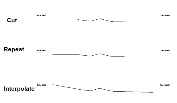
Cut. Selected by default. This proposes the cross-section profiles be cut should their strip width exceed the digital model definition or objects selected, in which case the profiles take on a width equivalent to the width entered or up to the point it is defined in the model.
Repeat. Using this option is recommended when there is excess strip width compared to the digital model and the surroundings are substantially similar to the last height obtained from the digital model. This is usually the case in terraced terrain or terrain having large flat surfaces, or when curved areas are cut in parallel fashion.
Interpolate. This option is used in order to complete the strip proposed when there is insufficient terrain in the strip width specified, the slope outside the working area is known and has similar gradients as those at the end of the profile. The program will interpolate using the slope of the last vectors cut until the height is raised to the profile's final length at the right and left sides.