
tcpMDT
Elevations from Long Section - MDT26
Elevations from Long Section
 | Command to execute in the CAD |
|---|---|
Vertical menu | MDT26 > Cross-sections > Utilities > Elevations from Long Section |
Ribbon menu | X.Sections > Utilities > Profile Elevations |
Command line |
This command enables changing the elevations of the cross-section cuts in terms of the long section. This option is particularly useful to equalize the cross-sections alignment elevation with that of the long section.
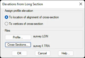
There are two different ways to assign elevations to the cross-section:
To Location of Alignment of Cross-section
This command is used to establish how the cross-section alignment elevation, the long section elevation of the corresponding station, and that of the rest of the vertices, increases or decreases in terms of the elevation difference between the cross-section and the longitudinal.
Below is an example of this command executed.
Example: For the next long section:
      0   125.546   MDT

     50   135.265   MDT

150.238   137.568   MDT
The cross-section cut for station 50 would be:
**BEFORE** **AFTER**
50 -5.5 134.568 50 -5.5 135.633
50 0 134.200 50 0 135.265
50 6 133.954 50 6 135.019
To Vertices of Cross-section
This command is useful to equalize the elevations of the profile with the elevations of the cross-section alignment. The program assigns to each alignment vertex the height corresponding to the long section of each cross-section cut.
Example: For the following long section:
      0   125.546   MDT

     50   135.265   MDT

150.238   137.568   MDT
The cross-section cut for station 50 would be:
     **BEFORE**                    **AFTER**

50   -5.5         134.568   50     -5.5        134.568

50   0            134.200   50     0           135.265

50   6            133.954   50     6           133.954
For cross-section vertices with no long section elevation, we insert the elevation of the long section and assign it to the corresponding cross-section.