
tcpMDT
Alignments - MDT26
Alignments
The parameters that determine horizontal alignment behavior include:
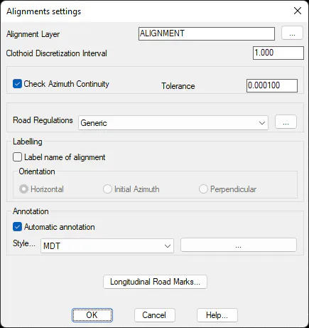
Alignments Layer (ALIGNMENT). Allows one to name the layer where horizontal alignments will be drawn. The name can be entered in the relevant text box or selected from a list of existing layer names by clicking on the Select button.
Clothoid Discretization Interval (1.0). Interval used in the alignment drawings of clothoid-type sections, expressed in meters. It only affects the drawing and has no influence the calculations' accuracy.
Check Azimuth Continuity. Activates the checking of azimuth continuity when converting a polyline into an alignment. It is obligatory that sections before a curved section have the same azimuth as the entry into the curve. This condition should also be met for the curve exit and subsequent section.
Azimuth Tolerance (0.0001): Tolerance in hundredths of a second so that two sections are considered as tangential. If the difference between the final azimuth of a section and the initial azimuth of the following section is greater than this value, a warning is issued about the error.
Road Standards
We can set the road standards of the country where we are going to work; in addition, for each country we will be able to configure its own road standards.
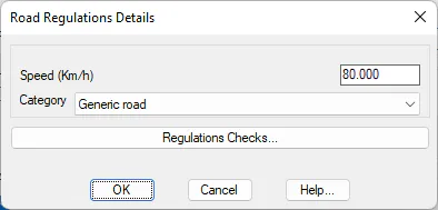
Speed (Km/h). Project design speed. Affects superelevation.
Category. Road category within those predefined which match the Road Regulations.
Under this option we can customize the error configuration for the standards on the ground plan. By executing the command Alignments > Utilities > Check Rules, MDT will only show those errors which are enabled under this option. If there is any error when checking the standards and we have it disabled, it will not appear on the final list. Consult the reference manual for details about this command.
Labelling
We configure the possibility of labeling the name of the alignment. In the case of activating the labeling, we have three options in terms of the orientation of the text to be drawn.
Horizontal: Label the name of the alignment horizontally. The insertion point will correspond to the starting point of the alignment.
Initial azimuth: Label the name of the alignment with an insertion angle equal to the initial azimuth of the alignment, that is, the text will be parallel to the initial alignment of the alignment.
Perpendicular: Draws perpendicular to the initial azimuth of the alignment with the insertion point corresponding to the initial coordinate of the alignment.
Annotation
Dialog box that shows the configuration parameters used to annotate alignments.
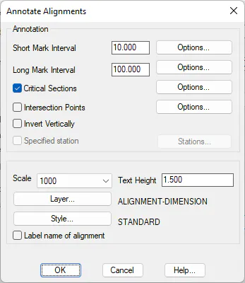
Short Mark Interval (10.0): Distance in meters between the short marks drawn on the alignment.
Long Mark Interval (100.0): Distance in meters between the alignment's long marks.
Unique Points (On): Activating this option draws the marks on the alignment's vertices.
The three kinds of alignment marks can be configured through their corresponding Options buttons.
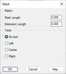
Mark Length: Dimension of the line representing the mark.
Extension Length: Dimension of the extended line on the opposite side of the alignment.
Texts. Allows one to write texts on the marks and, should this be done, choose between placing them to the Right or to the Left of the alignment. In the case of unique points, one can also indicate if the radius and parameter values should be written on the Inside or Outside of the sections.
Intersection Points (Disabled): Indicates whether to dimension the points of intersection with other alignments of the current project.
Invert Vertically: Reverse the labeling of texts.
Specified Station (Disabled): Ability to specify additional stations to be dimensioned.
Scale (1:1000): Scale factor that affects the size of the dimensioning texts.
Text Height (1.5): Height of alignment text labels.
Layer. Allows one to select the layer where the lines and the texts that make up the dimensioning will be drawn.
Style. Style of the dimensioning texts.
Longitudinal Road Marks
From this option we have the possibility to configure the horizontal marks to draw on the road. When accessing this option, we will see the following window:
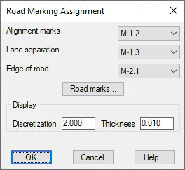
Alignment marks : Selection of the road mark assigned to the alignment position.
Lane separation : Road mark assigned to the separation between lanes, this road mark will be drawn as many times as lanes exist per direction.
Edge of road: This road mark will be drawn in the most external lane, in both directions of the road.
Discretization: When drawing the road mark, will be drawn with a polyline, this value represents the discretization of the polyline to improve the representation.
Thickness: Thickness of the texture of the road mark in the CAD drawing.
Road Marks...
From this option we have the possibility to configure the different road marks as well as to add new configurations.
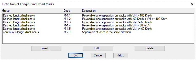
We have the option to Insert, Edit or Delete Road Markings.
For each road mark to be defined, we have the following options:
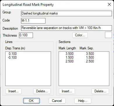
Group: Name associated with the road mark.
Code: Code representative of the road marking. It usually has a correspondence with the Road Regulations.
Description: Brief description of the design of the road mark.
Thickness: Width in the drawing of the road mark.
Lines: We indicate the number of lines to represent, in the image we have a road mark in the axis position.
Sections: In the case that it is a discontinuous mark, we define the length with which each section of the mark is repeated, in this case we have marks of 3 meters in length with a separation between marks of three meters. This configuration is repeated cyclically.