
tcpMDT
Surveying - MDT26
Surveying
Shows the configuration parameters for the program's Surveying Module.
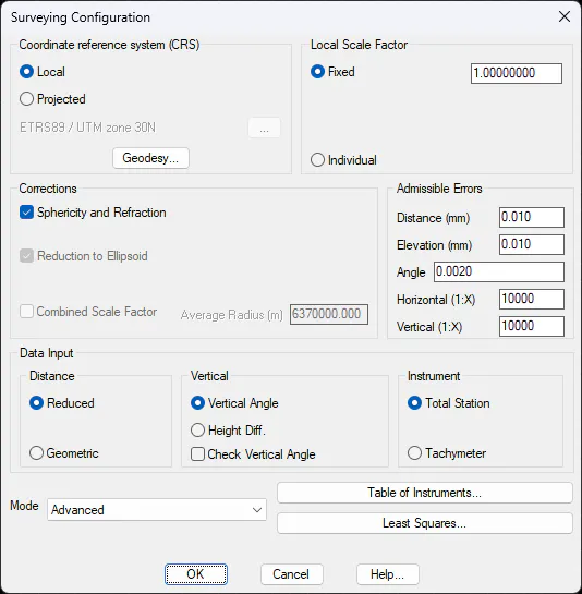
Coordinate Reference Systems (crs)
Specify the coordinate reference system type in which the default program will work, Local or Projected.
If we select Projected, it is needed to choose the projection system to be used. Default value is EPSG code 23030, corresponding to ED50 / UTM zone 30N. For more detail see Geodesy chapter in Surveying manual.
Geodesy
The geographic coordinate format is configurable and has the following options for setting input and output settings:
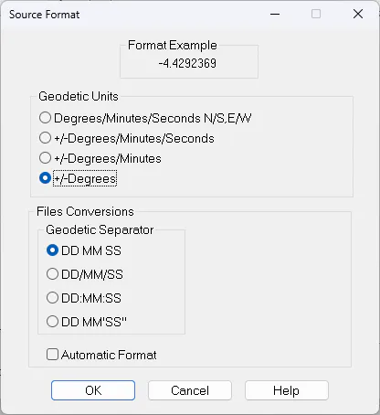
The supported formats are as follows:
Degrees/Minutes/Seconds NS-EW Example : 36 40 34.564 N
+/-Degrees/Minutes/Seconds Example : -4 25 12.3424
+/- Degrees Example : -2.23541
where the separator of degrees, minutes and seconds, for the first two formats, can be:
' ' Space
'/' Slash
':' Colon
' ° ' '' ' Degrees, minutes, and seconds symbols. For minutes and seconds the symbol is single quotation marks and double single quotation marks respectively.
If the Automatic Format box is checked , the program will read any combination of these formats. This option is only available as a source or import format.
It is also possible to establish two important properties that are involved in the calculation process.
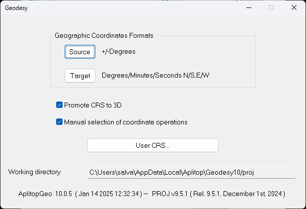
Convert SRC to 3D: If this option is enabled, the program will attempt to find an equivalent 3D coordinate system for the 2D systems involved in the calculation. It could be the source system, the destination, or both.
Manual selection of coordinate operations: By default, the program uses the most accurate set of coordinate operations for the calculation area. When this option is activated, the program will display, in a list, all the coordinate operations available to convert and/or transform from the source system to the destination, along with the precision (in meters) and the grid files (if involved in the calculation) associated with each set of operations.
In addition to the coordinate reference systems available for each authority, the module allows you to define user systems in WKT format. To access the screen that allows you to manage these systems, you must press the user SRC button...
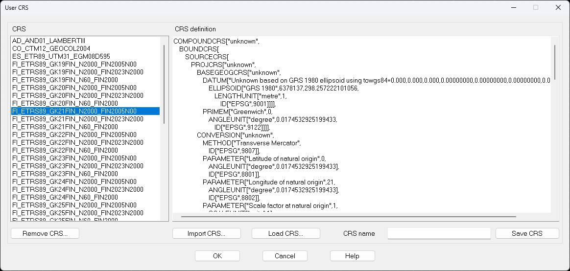
On the left side of this screen is the list of available user SRCs, and on the right side, the WKT definition of the system selected from the list.
To edit an existing user system, simply select it from the list and manually modify its parameters in the SRC Definition text box. You can also create a new one, by entering the full definition manually, from the definition of an official system, selected using the Load SRC button... or, importing it from a file, by clicking on the Import SRC button....
In one way or another, you can create or replace the new SRC by entering the name in the SRC Name box and pressing the Save SRC button.
To delete an existing coordinate system, select from the list and press the Delete SRC... button.
Local Scale Factor
This template enables us to indicate a scale factor for a local system. Selecting the Fixed option establishes the scale introduced for all the stations, which is 1.0 by default. The Individual option uses the scale assigned to each station. In this case, the new stations calculated are created with a scale factor of 1.0.
Corrections
Allows one to activate or deactivate the corrections applied to different program calculations. The formulas used in each specific case can be queried in the Surveying Module's reference manual.
The following types are available:
Sphericity and Refraction (On): Value added to the height difference, allowing the optical effects of sphericity and refraction in observations to be corrected.
Reduction to Ellipsoid (Off): Value applied to distance that adjusts for errors arising from survey's projection to the ellipsoid.
Combined Scale Factor (Disabled): This is the factor resulting from multiplying the anamorphosis by the scale factor owing to the height. The mean radius of the Earth must be entered in meters in the working area.
Admissible Errors
These are the limiting values below which the system calculations made are considered as admissible. If these thresholds are exceeded, the program will indicate the differences with a mark.
Distance (0.01): Maximum admissible horizontal difference (meters).
Height (0.01): Maximum admissible height difference (meters).
Angle (0.002): Maximum admissible angle difference (hundredths of a degree).
Horizontal (1:X): This allows the minimum horizontal closing error to be indicated for traverse compensation. For example, a value of 10000.0 is one part of 10000.
Vertical (1:X): This allows the minimum vertical closing error to be indicated for traverse compensation. For example, a value of 15000.0 is one part of 15000.
Data Input
The parameters appearing below allow one to choose among different data input and presentation modes, so that they are more natural for users. The program stores these values in a single format, so that the configuration can be easily changed without affecting the information's integrity.
Distance (Reduced): Allows one to choose between horizontal or Reduced distance, in addition to sloped or Geometric distance.
Vertical (Vertical Angle): Allows one to choose between showing each observation's Vertical Angle or Height Difference. If the check Vertical Angle box is marked, the program checks whether the vertical angles observed are between 50 and 150 hundredths of a degree for direct circles and between 250 and 350 hundredths of a degree for inverse circles.
Instrument (Total Station): If the Total Station mode is selected, every observation will be made up of a horizontal angle, a reduced or geometric distance, a vertical angle or height difference and a prism height. On the other hand, if the Tachymeter mode is selected, the program will show the thread 1, thread 2, horizontal angle and stake fields for each observation.
Mode
This option allows one to control the appearance of the Calculate Stations dialog box within the Surveying Module. If the default mode is Beginner, a simple dialog box is shown containing the essential calculation elements, while a wide range of calculation methods are available in Expert mode.
Instruments Table
Using the Instruments Table button, the menu can be accessed which allows the configuration of the values that mainly affect the standard deviations of the observations, essentially used in the adjustment methods by Least Squares.
These values can be customized for each Brand and Model.
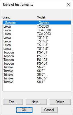
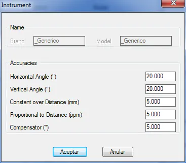
The default values are regarded as appropriate for the majority of cases though the documentation must be consulted regarding the technical characteristics of the equipment to enter the correct values.
Horizontal Angle* (*20.0): Estimated error when measurement horizontal angles in hundredths of seconds.
Vertical Angle (20.0): Estimated error when measurement vertical angles in hundredths of seconds.
Constant in Distance (5.0): Constant error made in measurement distances in millimeters.
Proportional in Distance (5.0): Error which occurs with distance measurement and which is proportional to the latter. Expressed in parts per million (ppm).
Compensator (5.0): Compensator accuracy in hundredths of seconds.
Least Squares
A menu allowing one to configure the parameters affecting all the least squares adjustment procedures in the surveying module can be accessed through the Least Squares button.
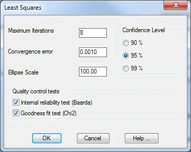
Maximum Iterations (8): Sets the maximum number of iterations that are allowed for the convergence of the iterative process in calculations. If messages of the type "The system does not converge" appear, this value should be increased, or the input data values checked.
Convergence Error (0.001): Maximum admissible error for coordinate increments obtained by the calculation process, in meters.
Ellipse Scale (100.0): Scale factor for drawing traverse and network error ellipses.
Confidence Interval (95%): Confidence Interval it is wished to be used in least squares calculations.
Internal Reliability Test (Baarda): This button enables the calculation of the internal reliability of the adjustment to detect gross errors.
Adjustment fitness test (Chi2): This button enables the calculation of the Chi-square test to ascertain whether there are any major differences between observables.
See the detailed description of these two tests in the Topography Manual.