
tcpMDT
General - MDT26
General
Shows the program's basic configuration parameters.
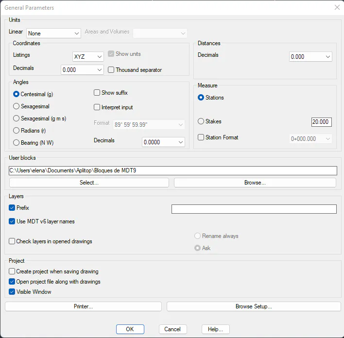
Units
In this section, the linear units to be used by the program are configured in the lists and files with results. The program distinguishes between two modes of operation:
Without specifying units: the program will not show the units in the lists, and it will not conduct any type of unit conversion when reading or saving a LandXML file or similar, in which the unit of measurement used is specified. Neither will any type of unit be shown in the lists, nor will the drawing units be considered, and the user is responsible for deciding whether the measurements are in meters, feet, etc.
Specifying a default unit (meters, feet, inches): when importing or exporting a LandXML file or similar, the program will conduct the necessary conversions between the source and destination files. Units suffixes (m for meters, ft for feet, etc.) may be included in the lists. In addition, the report may include unit suffixes (m for meters, ft for feet, etc.). Finally, in case of selecting feet as a linear unit, for the units of area and volumes you can choose between Feet or Yards.
Listings
In this section we will configure the preferred order of the components of the coordinates in the lists, in addition to the number of decimal places and if the unit of measurement is to appear in the column header. Finally, you can turn on comma to be displayed in the separation of thousands and millions in numeric values.
Distances
We can specify the number of coordinates of the distances appearing in the lists.
Angles
Units for representing the angles, it currently supports the following angular units:
Centesimal
Sexagesimal
Sexagesimal (degrees, minutes, seconds)
Radians
Bearing
Show suffix: With a suffix at the end of each of the numerical values the angular unit is indicated on which work is being carried out. The program will interpret it automatically.
Interpret input: If we place the suffix in accordance with the angular unit we wish to enter after the numerical data, the program will automatically interpret the angle irrespective of the angular system for which it is configured.
Format: In the event that "Sexagesimal (d m s)" is set as the angular unit, we establish the format in which we wish to represent the data.
Decimals: We indicate the number of decimals with which the configured angular unit is going to work.
Measurement
Generally speaking, we are always going to work with the measurement unit Stations; by contrast, in certain countries it is frequent to use other measurement units. This is the case of Brazil, for example, where it is very frequent to use the Stakes.
It is in this section where we will determine whether we are going to work with the Stations or the Stakes. In turn, for each measurement unit "Stake" we must specify the number of meters it is equivalent to and by default this value will be 20.
In addition, owing to compatibility on the lists with other programs, the possibility is also provided of representing the Station in the format 1+345.4567.
User Blocks
It allows to set up the folder containing program's blocks.
The path specified in this field indicate where the drawing which uses MDT in different options are stored. The directory can be specified by typing the path or by selecting the folder by pressing the Select button.
Browse. Pressing this button will access the MDT8 personal folder configuration.
Layers
Prefix: Prefix for all layers used in the program, so that in drawings with many layers the ones created by this application are easily found.
Use MDT v6 layer names: If we activate this option, we will enable the new assignment of layer names for MDT version 6 onwards. For more detail see option Utilities > Rename Layers.
Check layers to open drawings: In the case of using MDT6 layers configuration, if you open an existing drawing, there are two ways to proceed:
Rename always: The program will always rename the drawing's layers.
Ask: Program always asks if layers will be renamed to MDT6 new layer names.
Project
Create project when saving drawing: If this option is activated, the program will automatically ask users when saving any drawings not associated with an MDT project in which new project, they wish to save it.
Open project file along with drawings: When this box is activated, an MDT project will be opened each time a CAD drawing associated to it is opened
Visible Window: Controls the visibility of the project window. If the option is activated, it will always be shown when there is an active project.
Printer
It allows you to set the values for printing parameters in Windows, text and file mode for all listings generated by MDT.
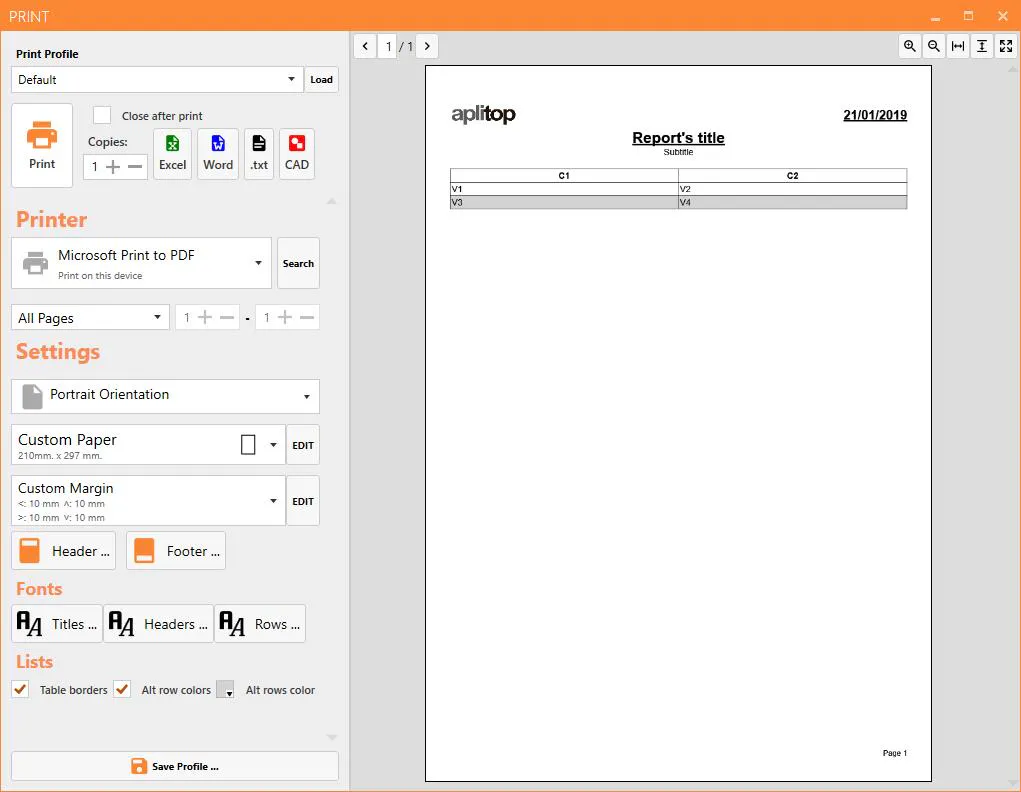
Print Profile: Lets you select a previously saved print layout that can be loaded to restore these settings: headers, fonts, page size, margins, etc.
Print: Send the document for printing to the selected printer.
Close after printing: If activated, the dialogue box will close once printing is finished.
Copies: The number of copies to print of the current document.
Excel, Word, .txt and CAD: Export the document to any of these formats: .xls (Excel), .docx (Word), .txt (Plain text document) and to the CAD drawing software.
Printer: Allows you to choose one of the printers connected to your computer as the destination for printing the document. It is also possible to select the system printing dialogue box, where you can adjust more settings for any of these printers. With the Search button, the list of printers will be updated (in case you have connected a new one when the dialogue box was already loaded).
All pages/Selected pages: We can specify the range of pages we want to print or print the entire document.
Orientation:
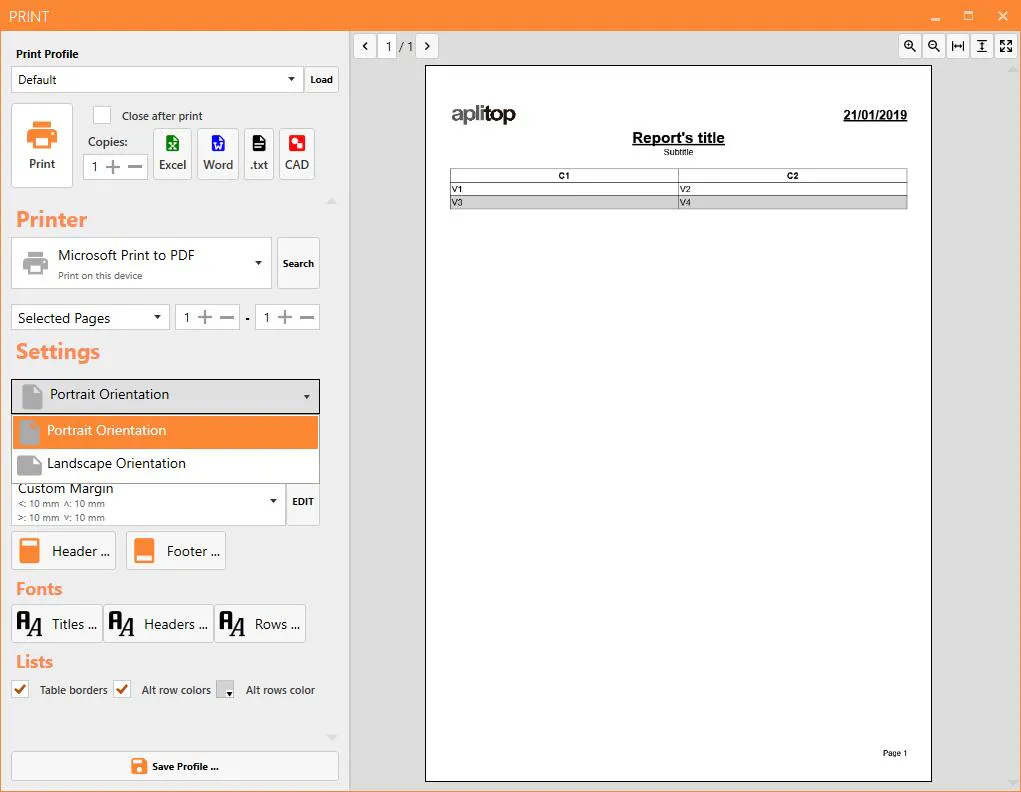
Paper orientation
Vertical: The height of the page will be the highest value of the paper.
Horizontal: The width of the page will be the highest value of the paper.
Paper
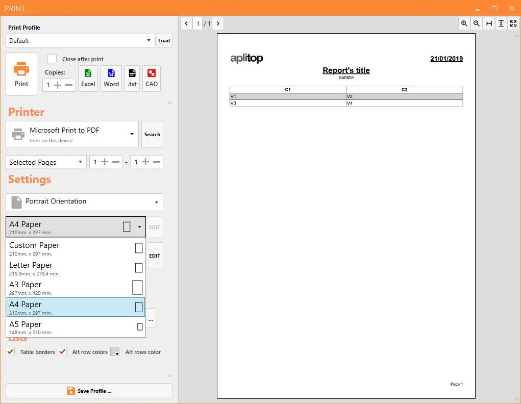
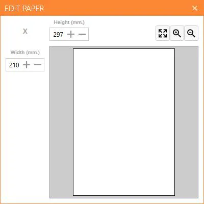
It lets you select the paper size, there are some predefined sizes, but it is possible to manually set the paper size. Selecting Custom Paper will activate the EDIT button, where you can access the paper size editor and set the width and height (in millimeters):
Margins
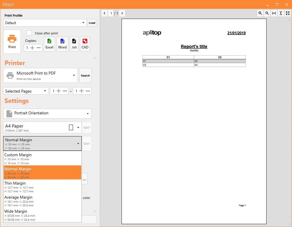
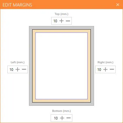
This lets you set the margins of the document. There are some predefined margins, but it is possible to set a custom configuration. To do this, selecting Custom Margin will activate the EDIT button, which will take us to the margin editor and can be set individually (in millimeters):
Header/Footer
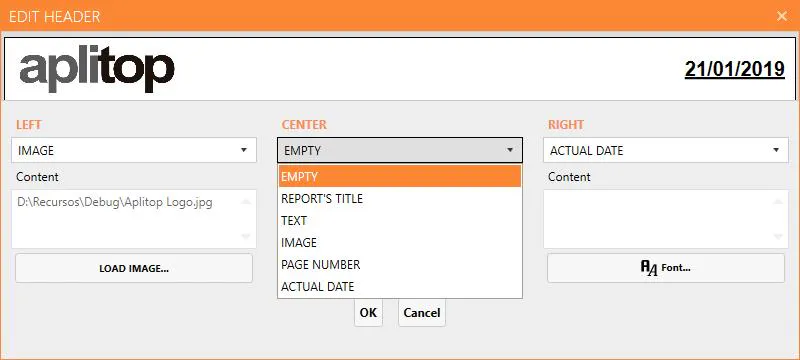
It allows you to set the header and footer of the document. You can set three blocks: left, center and right. The possible values of each blocks are:
Empty: Nothing appears in the block.
Report's title: The title of the report that is being printed is displayed.
Text: Custom text will be displayed, which will be specified in Content.
Image: A custom image will be displayed.
Page Number: The current page number will be displayed.
Actual date: The current date will be displayed.
It is possible to customize the fonts of each block with the Font button...
Both the header and the footer will be repeated at the beginning and at the end of each page of the document.
Font
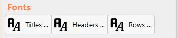
To define the sources that will be used in:
Titles: Titles of the report.
Headers: Headers of the tables that appear in the document.
Rows: Cells of the tables that appear in the document.
To edit any of these fonts, and for the fonts of the header/footer, the font editor is used:
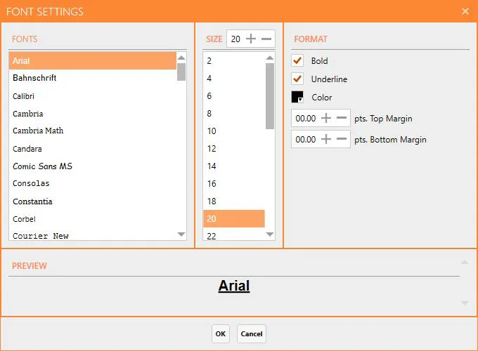
Fonts: Allows you to choose a system font for the text.
Size: Sets the size (in point sizes, pt.) of the text. It can be from the list of predefined sizes or entered manually.
Format: Lets you adjust the presentation of the text by adjusting:
Bold: If set, the text will appear in bold.
Underline: If set, the text will appear underlined.
Color: The color that the text will have.
Top margin: Sets the upper margin of the text (in font points, pt.)
Bottom margin: Sets the lower margin of the text (in font points, pt.)
Lists
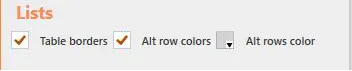
This allows you to adjust the presentation of lists, which are shown in the document as a table:
Table borders: If set, tables will have grid edges.
Alt row colors: If set, tables alternate the color of the rows.
Alt rows color: The background color of alternate lines.
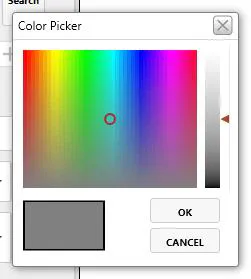
For the colors of the alternate lines, as well as for the colors of the fonts, the color selector will be used:
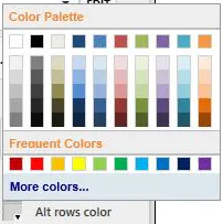
Color is selected by clicking on one of the colors of the palette. By clicking on: More colors the advanced selector will appear, where it is possible to choose from a wider range of colors:
Save profile

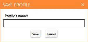
This allows you to save the current settings in a print profile. To do this, a dialogue box will appear that will require you to give a name to said profile:
Once saved, the profile will appear in the list of profiles at the beginning of the print dialogue box:
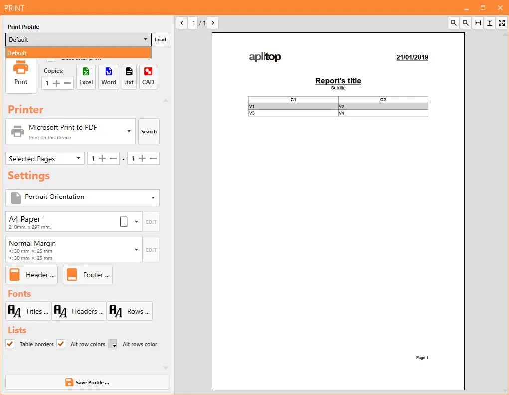
Once the profile is selected, pressing the Load button will restore saved settings.
The dialogue box always remembers the settings established at the time it was closed.
The print profile stores the following settings:
Orientation
Paper size
Margins
Header and Footer settings
Fonts of Titles, Headers and Rows.
List settings
Export: Excel, Word, .txt and CAD
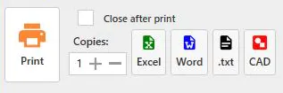
It is possible to export the document to several formats:
Excel
Word
Txt
Printing CAD drawings
In the case of Excel and Word, the settings established in the printing dialogue box will be used: fonts, table borders, paper size and margins (in the case of Word), etc. For .txt there is no configurable format, since it is plain text without formatting.
In the case of printing CAD drawings, it will show its own configuration window, described in the following section.
Printing Drawings
By clicking the CAD button, we can configure the printing of the drawing. In this configuration window we can set the different settings necessary to carry out the printing of the CAD drawing itself.
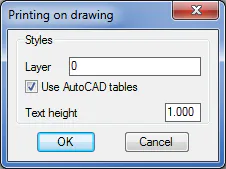
Layer: Layer in which the list will be printed in the active AutoCAD drawing.
Draw Grid: If this option is activated, MDT will draw a grid for each of the elements to be listed.
Use AutoCAD Tables: If this option is activated, the program will use AutoCAD Table objects when printing in AutoCAD 2005 or above.
Text Height: Height of texts to be printed.