
tcpMDT
BIM - MDT26
BIM
From this section we have the possibility to configure the files and databases used for the management of export to BIM. For more details, consult the BIM section of the Reference Manual.
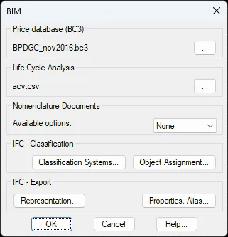
Price Database (BC3): We select the price database that the default program will use. It is a file with BC3 extension and its usefulness is the assignment of the Works Units to the different components generated in the software (surfaces, roadbed layers ...).
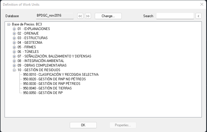
In the following image you can see a capture of its contents. With the BIM command > Price Database, we have the possibility to view or modify it.
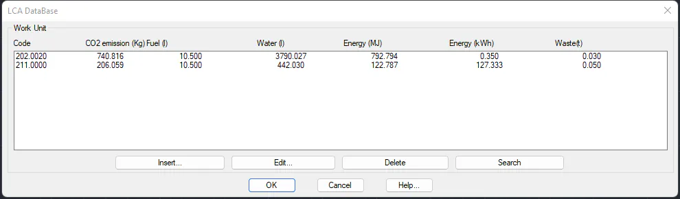
LCA Database: We select the database related to Life Cycle Analysis, as in the previous database, after assigning to the different components generated in MDT, we have different tools to generate the corresponding lists.
Then we see a capture of it, with the BIM command > LCA Database we can manage it.
IFC -- Properties: Selection of the property file. These properties we have the possibility to assign it to the different elements (road alignments, surfaces, earthworks ...) for export to IFC.
Both the management of this file and the assignment is done from the BIM menu.
Nomenclature Documents: In the export to IFC, possibility that the name of the IFC file to be created is automatically constructed from a certain encoding.
IFC- Classification: Classifying entities available for subsequent assignment to the different MDT elements. By pressing the button "Classification Systems ..." we have the possibility to manage the classifying entities.
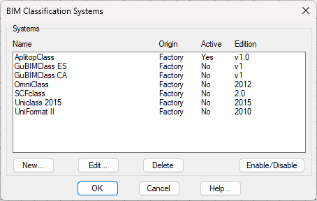
It shows us a list with the entities loaded by default with the installation of the application, and we can also add new classifications.
By clicking New, it allows us to add a new classifying entity by importing an XML file and filling in the rest of the relevant information.
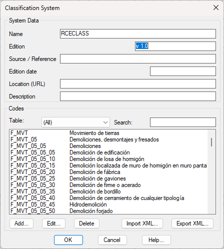
Within the Classification System dialog, besides adding information about the entity, we can add new Codes, edit them, and delete them, as well as import an XML file or export it.
By clicking Edit, it shows us the previous dialog with the data and codes of the selected entity, and we can add, edit, or delete codes, as well as export XML.
By clicking Delete, we remove a classifier entity from the list.
By clicking Activate/Delete, it sets a classifier entity as active or not.
By pressing the "Object Assignment ..." button, we have the option to assign MDT objects codes from one or multiple classification systems.
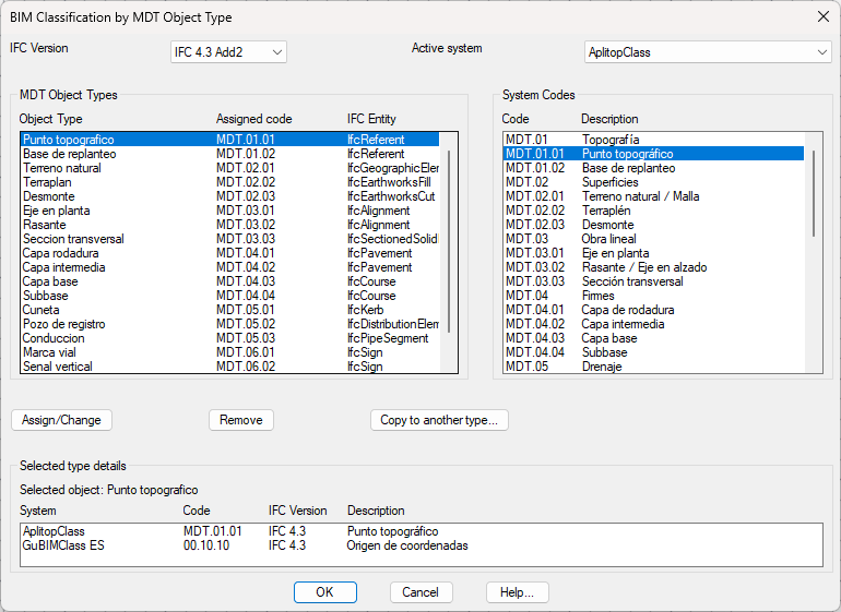
In the dialogue BIM Classification by MDT Object Type, we can choose the IFC Version and the active classification system to make the assignments.
MDT Object Types, listing the objects used in MDT, the assigned code of the selected entity, and the IFC entity corresponding to it according to the selected scheme.
System Codes, lists of the codes and the description of the selected classification system.
By pressing the Assign/Change button, a relationship is created between the element selected in the first list and the one selected in the second list. Pressing it a second time on an object that already has an assignment updates that assignment with the new element selected in the second list.
By pressing the Remove button, the assignment of the element selected in the first list is deleted.
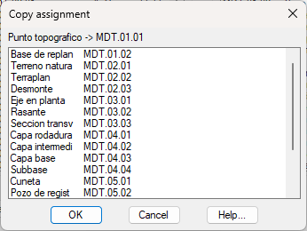
By pressing the Copy to another type button, a dialogue appears with a list of MDT Objects that have assignments, so you can select an element, and the assignment of that element will be copied to the Object selected in the main dialogue.
In the Selected Type Detail, we can see the system, Code, IFC Version, and description of all the assignments that the selected object has in the MDT object type list.
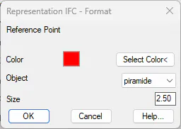
Representation, allows the user to select the 3D element that will represent the following MDT objects within the IFC file:
Reference Point
Topographic Point
Setting Out Bases
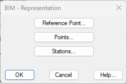
By pressing any of these three buttons, we can select the Color, the Object to draw and the Size of it.
Propiedades - Alias
The command manages the file BimPSetTable.dat (located in config\\es\\BIM\\ and config\\en\\BIM\\), which is an alias table that translates the name of a property from a Pset or Qto to an internal identifier of a "calculator" — a function in the IFC export engine that calculates the value automatically from the geometry or data of the MDT object.
This table only intervenes in properties whose "Value origin" is configured as "Calculated MDT" (valueSource="CalculatedMdt") in their definition within a Pset/Qto (see the Edit Property window, documented in property_sets_cmd.md). For properties with Manual or Imported XLS origin this table is not consulted.
It is important to note that when a property has origin "Calculated MDT", the export engine completely ignores the normal override system across layers (instance > MDT type > XLS > Pset default value) and uses directly the value returned by the associated calculator in this table. If the property name has no entry in the table, or the calculator does not exist, the property is exported with an empty value (no error is produced).
File format of BimPSetTable.dat (plain text, comments with #):
property_name = calculator_id
The property name is case-insensitive. Multiple different aliases can be defined that point to the same calculator identifier (for example area and area2d can both point to area2d_Surface).
[!info] Actual read/write location
The file is read first from the installation (Program Files) and, if it exists, from the user layer in AppData. When saving changes from this command, it is always written to AppData (never to the installation folder, which is not writable in standard installations); the factory copy is never modified.
Accessing the command
There are two ways to open the same window:
Direct command: type
IFC_EDITAR_ALIASPSETSin the AutoCAD command line.Configuration Menu: Configuration > BIM > button "Properties. Alias...", located next to the "Representation..." button within the "IFC - Export" group of the BIM configuration dialog. This button internally invokes a pass-through command (
IFC_EDITAR_ALIASPSETSEXT, hidden, with#prefix, not intended for direct user use) that forwards the call to the sameIFC_EDITAR_ALIASPSETScommand from the IFC module.
It is also accessible indirectly from the Edit Property window (see property_sets_cmd.md): when defining a property with Value origin = "Calculated MDT", the "Calc Table..." button in that window opens this same table, so you can create or review the alias of the property being defined without closing the edit dialog.
Main window — BIM Calc Table
Controls
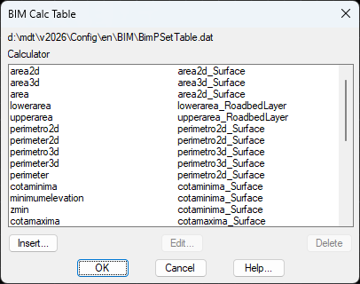
File path — Read-only text at the top with the full path of the
BimPSetTable.datbeing edited (always the write path in AppData).Alias list — List with two columns: property name and assigned calculator. Double-clicking a row opens the edit window for that entry directly.
Insert... — Opens the "Calc Entry" window in blank mode (with the first calculator in the list preselected by default) to add a new alias.
Edit... — Opens the "Calc Entry" window with the data from the selected row, to modify the property name or the associated calculator. Requires a row to be selected (the button remains disabled if no selection).
Delete — Removes the selected row from the list (the file is not written to disk until Accept is clicked). Requires a row to be selected.
Accept — Completely rewrites the
BimPSetTable.datfile in AppData with the current content of the list (includes a comment header with the list of available identifiers). Discards any row that does not have a property name or calculator.Cancel — Closes the window without saving any changes; the file on disk is not modified.
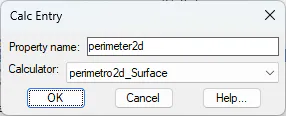
Calc Entry window
Controls
Property name — Free text field (editable). Must match exactly (case-insensitive) the name of the property defined in the Pset/Qto for the calculator to be applied during export.
Calculator — Drop-down list (popup) with all calculator identifiers currently available in the export engine (see table below). When inserting a new entry, the first calculator in the list is preselected; when editing an existing entry, the already-assigned calculator is automatically preselected.
[!warning] Check the preselected calculator when editing
The list of calculators in the drop-down is kept synchronized manually by developers with the actual calculators in the export engine. If an entry is ever edited whose calculator does not appear in the drop-down list, it will preselect the first item in the list instead of the actual assigned calculator — it is advisable to always verify that the calculator shown when opening "Edit..." matches what is expected before clicking Accept, especially in entries that were not created from this same dialog.
Available calculators
Identifier | Applicable object | Calculates | Factory aliases |
|---|---|---|---|
| Surface, Earthworks component | 2D area in plan |
|
| Surface | Actual 3D area (following the geometry) |
|
| Surface, Earthworks component | 2D perimeter in plan |
|
| Surface | 3D perimeter |
|
| Surface, Earthworks component | Minimum Z elevation |
|
| Surface, Earthworks component | Maximum Z elevation |
|
| Surface, Earthworks component | Length (Y extent) |
|
| Surface, Earthworks component | Width (X extent) |
|
| Surface, Earthworks component | Height (difference between max and min elevations) |
|
| Surface | Number of vertices |
|
| Surface | Maximum edge length |
|
| Earthworks component (Surface: pending) | Volume of the component |
|
| Earthworks component (Roadbed layer) | 3D area of the lower face of the roadbed layer |
|
| Earthworks component (Roadbed layer) | 3D area of the upper face of the roadbed layer |
|
| Earthworks component (Roadbed layer) | Official measurement thickness of the roadbed layer |
|
[!info] Behavior when object type does not match
If the type of object being exported does not match the one expected by the calculator (for example,volumen_Surfaceon a Surface instead of an Earthworks component), the calculator returns an empty string and the property is exported without a value, without generating any error.
Relationship with the rest of the BIM system
This table is the piece that connects the declarative definition of a Pset/Qto (property name + "Calculated MDT" origin, configured in IFC_PROPSETS) with the actual implementation in C++ of the export engine. Adding a new calculated property requires two steps: (1) define the property in the corresponding Pset/Qto with "Calculated MDT" origin from IFC_PROPSETS, and (2) create here the alias that links it to an existing calculator in the engine (new calculators themselves are implemented by developers, they are not configurable by the user).