
tcpMDT
Long Sections - MDT26
Long Sections
Shows the values affecting the commands used to obtain and draw long section drawings.
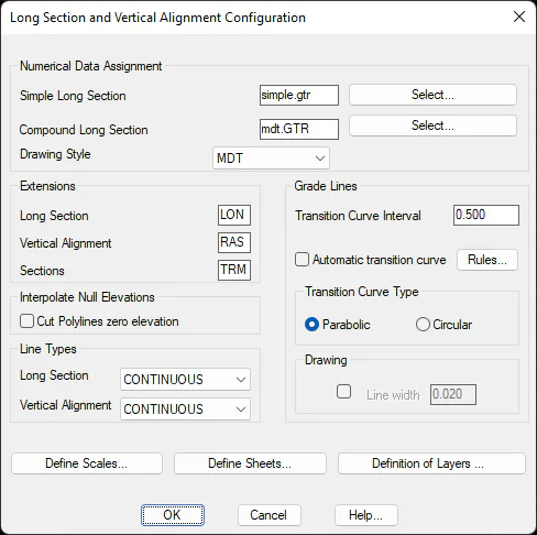
Numerical Data Assignment
Allows one to select the default numerical data files to draw Simple Long Section profiles (SIMPLE.GTR) and Compound Long Section profiles (MDT.GTR). These files may be edited using the Numerical Data Definition command.
Drawing Style: Enables us to select from different profile representation styles. For each profile the style will customize the labeling of the numerical data, texts, data prefixes to be labeled ....
Types of Lines
Profile: Default line type when drawing a longitudinal profile using the Draw Simple Long Section and Draw Compound Long Section commands.
Grade Line: Default line type when drawing a vertical alignment using the Draw Compound Long Section and Draw Vertical Alignment commands.
Extensions
Longitudinal Profile (LON) : Longitudinal profile file extension.
Grade Line (RAS) : Grade line file extension.
Segments (SEG): Segment file extension.
Grade Lines
Transition Curve Interval (0.5): Vertical transition curve representation interval.
Type of Transition Curve (Circular): Default transition curve type to be used with vertical alignment files. Two options are given: Circular and Parabolic.
Automatic transition curve: When this option is activated, on converting the polyline vertical alignments MDT will insert the curves automatically, thereby optimizing the same and preventing overlapping between the different vertices.
Rules
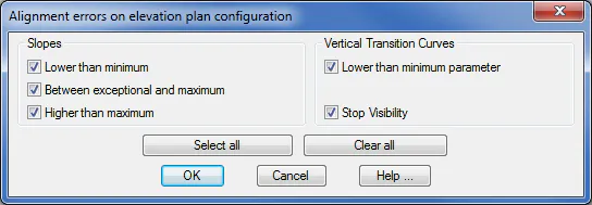
In this option, you can customize the configuration errors for road rules in elevation plan. After running command Vertical Alignments > Check Rules, MDT will show only those errors enabled in this option. If there exists any error in rules and it is disabled, it will not be shown in the final report. See more information in reference manual.
Interpolate Null Elevations
Cut Polylines with Zero Elevation (0): Establishes whether polylines having an elevation of zero are considered in the profile generation option in the cut layers option.
Drawing
Line Thickness (0.02): Sets the thickness for lines / polylines drawn by commands Draw Simple Long Section and Draw Compound Long Section.
Define Scales
This button gives access to a dialog box showing the scales available in the program.
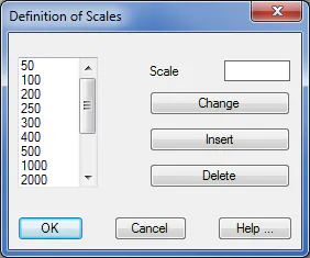
Change: Replaces the scale selected with one entered into the Scale text box using the keyboard.
Insert: Adds the scale typed into the Scale text box to the list of scales.
Delete: Deletes a scale selected from the list.
Define Sheets
Shows a dialog box where the dimensions of each of the sheet types can be set, along with the possibility of creating new formats. This information is stored in the Perfiles\Hojas.dat file in the Config directory.
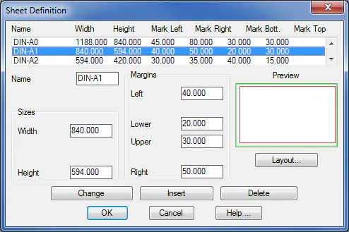
Change: Allows one to modify the format values for the sheet selected.
Insert: Adds a new sheet format to the list once the dialog box fields have been filled in.
Delete: Deletes the sheet format selected.
Name: Name of the sheet selected or to be defined.
Dimensions: Width and height of the sheet in millimeters.
Margins: Sets the sheet's Left, Right, Upper, and Lower margins in millimeters.
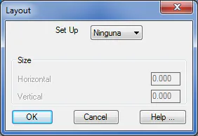
Layout: Sets the sheet's layout position, as well as its dimensions.
Definition of Layers
Dialog box to name the layers involved in longitudinal profiles. Allows one to enter a name by typing it in or choosing it from a list of available layer names via the Select button.
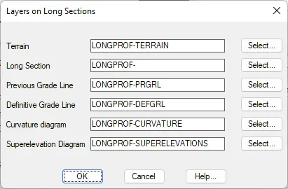
Terrain (TERRAIN): Name of the longitudinal profiles' terrain layer.
Long Section (LONGPROF): Name of the longitudinal profile layer.
Previous Grade Line (PRGRL): Name of the previous grade line layer.
Definitive Grade Line (DEFGRL): Name of the definitive grade line layer.
Curvature Diagram (CURVATURE): Name of the layer where the curvature diagram is drawn.
Superelevation Diagram (SUPERELEVATIONS): Name of the layer where the superelevations diagram is drawn.