
tcpMDT
Surfaces - MDT26
Surfaces
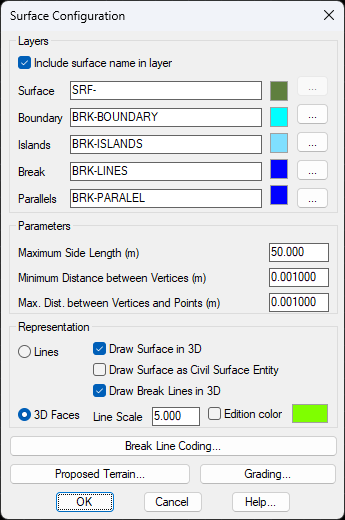
Shows the parameters which configure the behavior of the tools used to create and edit triangulations.
Layers
Allows one to name the different layers making up a drawing, or to select them from a list of existing layers.
Include surface name in layer: If we enable this option, the layer on which the surface is drawn will have the name of the surface file with the SUP- prefix.
Surface: Triangulation layer's name.
Boundary: Boundary layer's name.
Islands: Name of the layer where the break lines making up an island are drawn.
Break Lines: Name of the break lines layer.
Parallels: Name of the layer used in the Displaced Parallel command.
Parameters
Maximum Side Length (50.0): Indicates the maximum length allowed for the sides of external triangles, expressed in meters.
Minimum Distance between Vertices (0.001): Indicates the minimum distance between vertices for the contour line triangulation process, expressed in meters.
Maximum Distance between Vertices and Points (0.001): Maximum separation distance between a break line vertex and a point, expressed in meters.
Representation
Draw Surface in 3D (Off): Determines whether triangulation lines are drawn on the plan (off) or on the space (on).
Draw Surface as Civil Surface entity (Off): There is a possibility to draw the surface with this native entity of BricsCAD 20 or higher.
Draw Surface with Civil Surface Entity (Off): You can draw the surface with this native entity from BricsCAD 20 or higher.
Draw Break Lines in 3D (Off): Determines whether break lines are drawn on the plan (off) or on the space (on).
Line Scale (5.0): In order to make the presentation more coherent, the CAD LTSCALE variable is assigned a value proportional to the scale and multiplied by this field. Consult the CAD manual for further details about the utility of this variable.
Representation type (3D faces): The representation of the surface can be performed with line-type entities or 3D faces.
Edition Color: Color that is assigned to the triangles in the drawing if they are modified with the tools available for this purpose (Insert, Invert ...)
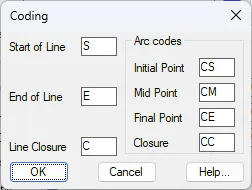
Break Line Coding
Shows a dialog box where the codes that appear as break line point suffixes are configured, so that they can be automatically interpreted in automatic drawing from codes. See Points > Codes > Draw from Codes command for further information.
Proposed Terrain
This button gives access to the dialog box allowing one to configure the elements of proposed terrain element profiles used to generate them and to draw solids. This information is stored in the Cross-Sections\CodSec.dat file in the Config directory.
Change: Allows one to modify the element selected.
Insert: Adds an element to a list after all the fields have been filled in.
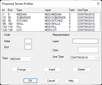
Delete: Deletes the element selected from a list
Codes: Initial and Final specify the code interval for an element selected or added.
Type: Element type, which can be MEDIAN, SUBGRADE, DITCH, CUT or FILL.
Layer: Layer associated with the element.
Color (1-red): Color associated with the element.
Line Type (CONTINUOUS): Line type of the element in question.
Grading
Shows a dialog box to select the names of the layers where polylines resulting from earthworks are drawn.
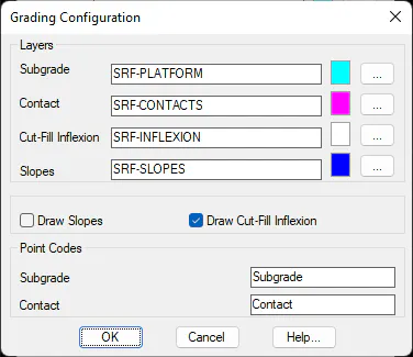
Subgrade (SUBGRADE): Name of subgrade layer.
Contact (CONTACTS): Name of contact layer.
Cut-Fill Inflection (SRF-INFLEXION): Name of the layer on which the lines separating the clearing areas from the embankment areas will be drawn.
Slopes (SLOPES): Name of slope layer.
If the Draw Slopes box is not marked, the polylines defining slopes are not drawn.
Point Codes
Subgrade: Code assigned to the point which forms part of the subgrade boundary.
Contact: Code assigned to the points created in the contact with terrain.