tcpMDT
Networks - MDT26
Networks
This option will allow us to configure all the parameters related to the management and drawing of the elements related to the Networks module. Validating this configuration option will redraw all existing nodes and pipes in the drawing according to the new parameters specified.
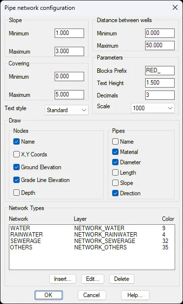
Slope: Minimum and maximum values between which the slope of the pipe section is permissible. In the event that the pipe section is not among these slope values, in the list of the same we will see a (*) in the slope value.
Covering: Minimum and maximum values between which the difference in elevation between the ground and the pipe section (depth) is manageable. In case this depth value is outside the limits, in the list of sections, a (*) will appear in the corresponding section.
Distance between wells: We establish the minimum distance between wells of a pipe section. As in the previous parameters, a distance less than or greater than that specified in these values will be reflected in the list of pipe sections.
Blocks Prefix (RED_): Prefix of the blocks corresponding to the insertion of Nodes. These blocks must be located in the MDT Blocks folder. Valid blocks for the insertion of the Nodes will be considered, all those whose name has the prefix specified here.
Text Height (1.5): Height of the texts associated with the nodes and pipe sections.
Scale (1000 ): Scale of drawing of the pipe nodes.
Draw
In this section we will activate those attributes that we want to be labeled both in the drawing of the nodes and the pipe sections.
Nodes:
Name: Name of the node.
X,Y Coords: Node insertion coordinates.
Ground Elevation: Ground elevation at the insertion point of the node.
Grade Line Elevation: Grade line elevation at the insertion point of the node.
Depth The depth of the pipe node. This value is the difference between the grade line elevation and the ground elevation
Pipes:
Name: The name of the pipe section.
Material: Pipe section material.
Diameter: Diameter of the pipe section. It is labeled in millimeters.
Length: Length of the pipe section between two nodes.
Slope: Slope of the pipe section between two nodes.
Direction: the direction that would carry the contents of the pipe according to the slope of the pipe is labeled with an arrow
Network Types
In this section we define the types of networks with which MDT will work, the networks established by default are:
Water
Rainwater
Sewerage
Other
With the Insert, Edit and Delete buttons we can customize the different networks with which we are going to work.
By pressing the Insert or Edit button, the following window will appear in which we will configure the new network to insert or edit.
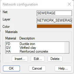
Network: Name of the network.
Layer: Layer of the network to be defined.
Color: With the color palette, we can select the color of the layer established for this network.
Materials: Each Network will have associated a series of materials. In the definition of the pipe section, we will indicate the material of which it is composed.
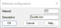
This list of materials is customizable by the user and must indicate the name of the material as well as the initials of it. These initials are those that will be used in the labeling of the pipe sections in the drawing.