tcpMDT
Templates - MDT26
Templates
Geology
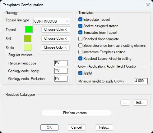
Topsoil line type: Selection of CAD line type to represent organic soil in drawing.
Topsoil: Color for topsoil.
Soil: Color for Soil geology layer.
Shale: Color for geology layer Transit.
Colors. It offers the possibility to change the colors of the natural soil layers, the grade and firm ground and through the palette of colors displayed by pressing the Choose Color button.
Templates
Interpolate Topsoil: If this option is enabled, the thickness of the organic soil will be interpolated when defining the sections.
Analyze assigned station: If it is enabled, when processing the sections, the program will also analyze the stations at which any kind of section assignment has been carried out.
Templates from Topsoil: If this option is enabled, the slopes of the section will be constructed from the geology layer, if it exists.
Roadbed slope template: If this option is activated and the natural terrain cuts the slope of roadbed, at that point, the construction of the section will finish.
Roadbed layers. Graphic editing: When this option is enabled, the definition of the roadbeds will be graphically displayed.
Slope clearance berm as a cutting lement: If this option is enabled and the existing ground intersects the roadbed slope, the cross-section construction will terminate at that intersection point.
Minimum Height for Applying a Crown: With this option, you can control the application of the crown element so that it is only applied when the cut slope reaches a minimum height.
This height is measured from the slope starting point to the ground elevation at the same offset distance from the centerline.
Roadbed Catalogue
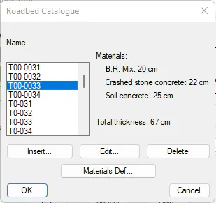
Default roadbed catalog for the definition of the roadbed layers in the definition of the typical section.
It is possible to select between different catalogs available according to the country and also edit or customize each of them.
Platform Vectors
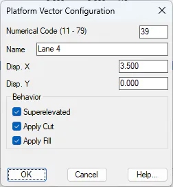
This dialog box defines the default codes and vectors that can make up a platform. Each of them has a numerical Code, a Name, Adjustments with regard to X and Y, and a value indicating whether it can be superelevated or not.
The codes should get larger from the alignment (value 0) to the profile ends, both to the left and to the right. The configuration can be changed through the Change, *Insert and Delete* buttons and is stored in the Perfiles\VecPlat.dat in the Config directory.
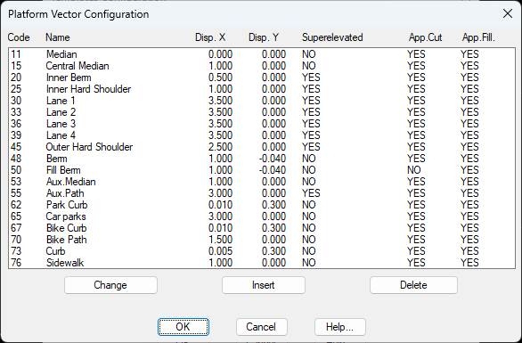
For each record, its properties are defined, which will serve as the default values for the roadway platform vectors in the typical cross-section definition.