tcpMDT
Maps - MDT26
Maps
Shows the configuration parameters for 3D grid drawings, slope maps and elevation maps.
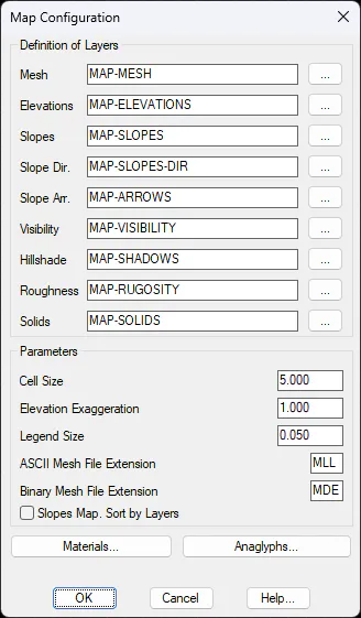
Definition of Layers
Grid (GRID): Name of the layer for drawing 3D grids.
Elevations (HEIGHTS): Name of the layer for the elevations map.
Slopes (SLOPES): Name of the layer for the slope map.
Slope Dir (SLOPE_DIR): Name of the layer for the slope directions map.
Slope Arrows (ARROWS): Name of the layer for the slope arrows map.
Visibility (VISIBILITY): Name of the layer for the visibility map.
Hillshade (MAP-RUGOSITY) : Name of the layer for the rugosity map.
Roughness (MAP-ROUGHNESS) : Name of the layer for the terrain roughness map.
Solids (SOLIDS): Name of the layer for drawing solids.
Parameters
Cell size (5.0): Default cell size.
Elevation Exaggeration (1.0): Default elevation exaggeration.
Legend size (0.05): Relative size of the legend's size compared to the screen.
ASCII Grid Files Extension (MLL): Extension of files used to export grids in ASCII format.
Binary Grid File Extension (MLB): Extension of files used to export grids in binary format.
Materials
Sets the materials to be used by the different commands found in the Maps/Render sub-menu. Consult the Reference Manual for further information.
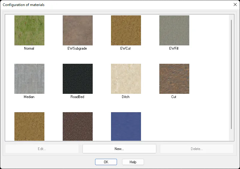
The Description of materials is merely informative. It describes the triangle type which will be applied to the material. The following kinds of triangles are differentiated according to the command with which they are generated.
Type MDT Command
Normal Create Surface
MTSubgrade Earthwork
MTCutting Earthworks
MTFill Earthworks
Median Modified Terrain
Platform Modified Terrain
Ditch Modified Terrain
Cutting Modified Terrain
Fill Modified Terrain
Color of material is used in case of not using the option to assign materials, in Draw Solids command. In this case the command execution is faster.
Texture indicates the type of texture that will be applied to the material in the representation of the modelling.
The Edit button lets you change any element. The New button to create new materials that can be assigned manually using the command Maps/Render > Assign Materials.
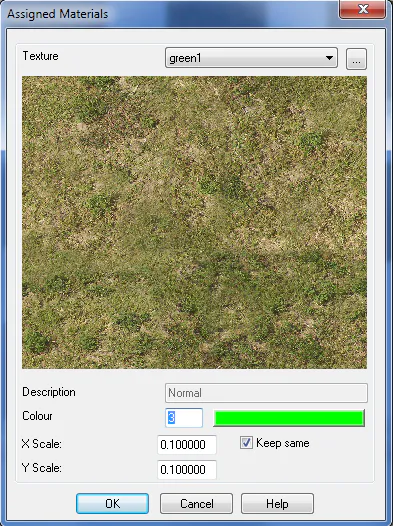
Texture: Name of texture.
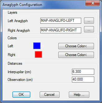
Anaglyphs
Parameters related to the Draw Anaglyphs command. The names of the layers where anaglyph curves will be drawn, as well as the colors to be used can be set. The Interpupilar parameter represents separation between the observer's eyes. The Observation parameter represents the distance from which the anaglyph will be observed.