
tcpMDT
Detect Geometric Errors - MDT26
 | Command to execute in the CAD |
|---|---|
Vertical menu | MDT26 > Plots > Detect Geometric Errors |
Ribbon menu | Plots > Plots > Detect Geometric Errors |
Command line |
This command analyses the plots in the drawing to find geometric problems that may affect subsequent operations (subdivisions, occupation calculations, cadastral exports, etc.).
When launched, the working mode is requested:
Single: A single plot is selected. The following dialog appears:
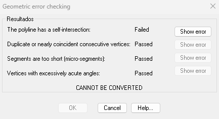
Four checks are displayed, each with a Passed or Failed result:
Self-intersection: the polyline crosses itself.
Duplicate vertices: consecutive vertices that are too close together.
Microsegments: sides shorter than the configured minimum length.
Acute angles: vertices with an internal angle below the configured minimum.
For each failed check, the Show error button becomes active. Clicking it draws a circle on the MDT_ERRORES_PARCELA layer at the problem location and zooms to it for easy identification.
Window / All: All selected plots (Window) or all plots in the drawing (All) are analysed at once. A report is printed in the command line with:
Individual errors per plot.
Overlaps detected between pairs of plots, including the overlap area.
If overlaps are found, a dialog opens listing all of them. Select an overlap and click Show overlap to zoom to the area and draw a circle on the MDT_ERRORES_PARCELA layer.
The thresholds (minimum segment length, minimum angle, vertex tolerance) are configured in the Plot Configuration dialog.