tcpMDT
Plot Report - MDT26
Plot Report
 | Command to execute in the CAD |
|---|---|
Vertical menu | MDT26 > Plots > Utilities > Plot Report |
Ribbon menu | Plots > Utilities > Plot Report |
Command line |
This command allows us to generate a report for the selected plots (one page per plot). When the command is executed, it will first prompt for the plots to include in the report, followed by a configuration window where the properties to be included can be set.
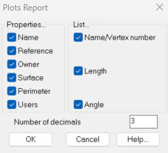
The Properties to Label panel refers to the values that will appear in the information box for each plot, inserted at the top of each page of the report.
Name. The plot identifier.
Reference. The plot reference (e.g. cadastral reference).
Owner. The name of the plot owner.
Area. The plot area, in the units specified in the configuration.
Perimeter. The plot perimeter.
The List panel allows you to specify the fields to be included in the detailed listing for each plot.
Vertex Name/Number. The point number matching each vertex of the plot will be shown, if one exists. Otherwise, a sequential number will be labelled for all vertices of the polyline, starting at 1.
Side Length. The length of each side of the plot will be labelled.
Side Angle. The internal angle formed by the sides adjacent to each vertex of the plot will be labelled.
Finally, the Number of Decimal Places field allows you to specify how many decimal places will be used for real numbers.
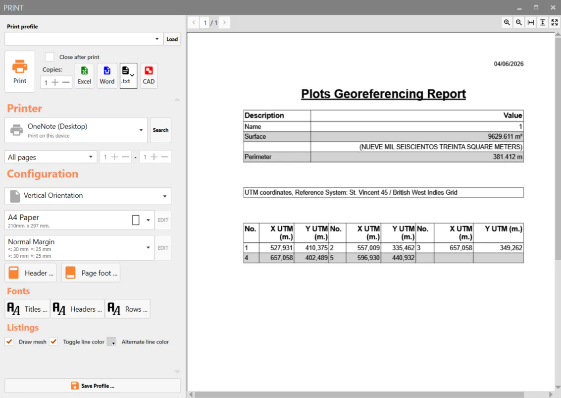
Once all parameters have been configured, a report similar to the one below will be displayed, with the option to send it to a printer or export it to other formats.