
tcpMDT
Edit Pool - MDT26
Edit Pool
 | Command to execute in the CAD |
|---|---|
Vertical menu | MDT26 > Plots > Other Constructions > Edit Swimming Pool |
Ribbon menu | |
Command line |
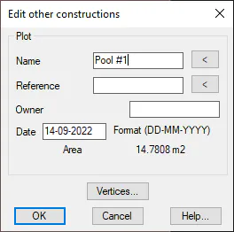
As with editing Buildings, with this command you can edit the properties of a Pool. The parameters Name, Reference and Date are those that directly affect the export to GML.
Vertices
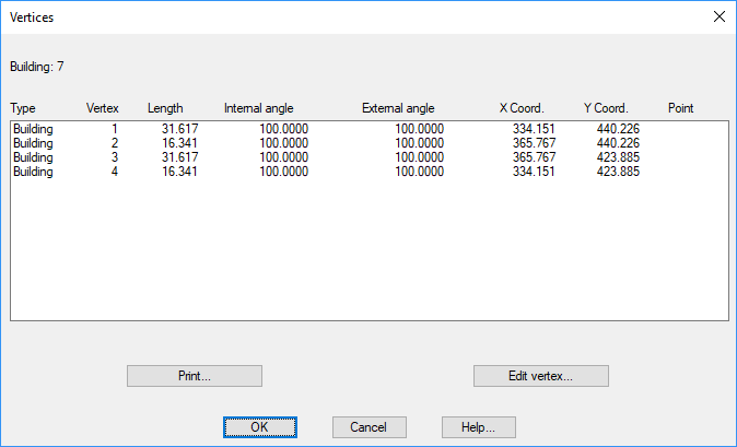
With this option you can see the information of all vertices of the pool.
Among other data, the length of each side is shown, as well as the coordinates of each vertex.
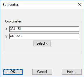
With the Edit vertex button, you can edit any vertex of the pool as well as change its coordinates. Activating the dialogue box, if the coordinates of a vertex have been changed, the pool will be updated with its new coordinates.
Generate 3D Constructions
This option will allow us to represent in 3D the buildings, the origin of the buildings can be Buildings created with the tools of MDT plots or simply closed polylines that represent the contour of the construction.
2D Constructions
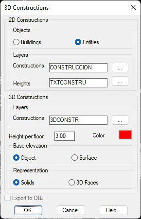
In this section we find the elements that we are going to convert to 3D, according to the parameters described below.
Objects: Elements of the drawing to convert to 3D.
Buildings: In the event that there are MDT Buildings objects in the drawing, this option will be activated by default.
Entities: With this option we will have the possibility to convert into 3D any closed polyline existing in the drawing.
Layers: It will only be enabled in the case of selecting the Entities option as Objects, in which case it is necessary to specify:
Constructions: Layer in which the polylines are closed to convert to 3D.
Heights: Layer in which the texts that refer to the number of floors of the polylines to be converted are located. This Height per floor value can be specified in both roman and decimal numbers.
In the case of selecting Buildings, the number of floors is automatically read from the building definition.
3D Constructions
In this section we indicate the characteristics of the 3D objects that will be created from the buildings selected in the previous section.
Layers: Layer on which the new 3D object will be drawn.
Height per floor: Value assigned as height to each of the floors of the building.
Color: Color of the 3D building to be created.
Base elevation: There are two possibilities in relation to the base dimension of the polyline or building.
Object: Dimension of the building to be converted.
Surface: The base of the 3D building will have the elevation of the surface.
Representation. As for the representation of the building in 3D, in terms of the type of representation, we have two options:
Solids: A solid CAD object is created.
3D Faces: The 3D building is drawn with CAD 3D Face entities.
Export to OBJ: In the case of selecting the 3D Faces representation option, we have the possibility to create an OBJ file and thus view the file created in 3D image editing software.
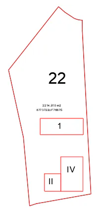 | 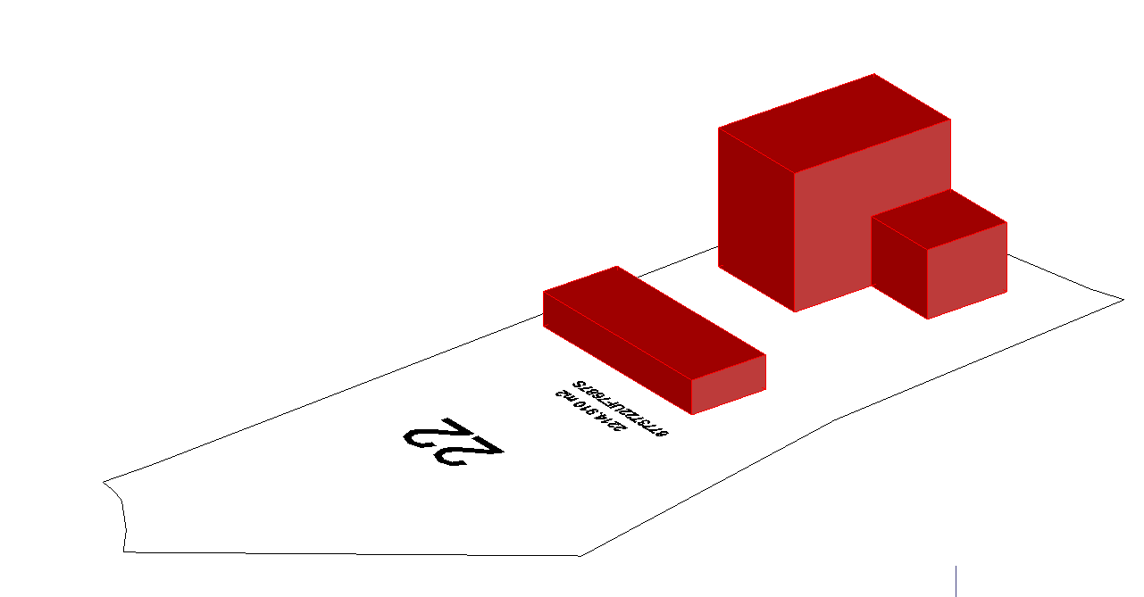 |
|---|---|
In the image on the left we see three closed polylines, which, some in Roman numerals and one in decimal, indicate the number of plants of the same.
In the image on the right, you can see the final result after the execution of this option.