tcpMDT
Grid - MDT26
Grid
 | Command to execute in the CAD |
|---|---|
Vertical menu | MDT26 > Points > Create Points > Grid |
Ribbon menu | Points > Create > Mesh |
Command line |
With this command you can quickly create a set of points, according to a Rectangular or Triangular arrangement. The initial window allows you to specify the X and Y intervals of separation between the points. If the Triangular grid option is enabled, the previously entered Y interval is recalculated. By default the program will create a rectangular grid, but by activating the Boundary option and selecting a polyline, points will be created within the polyline. You can also enter the Name, Code and Level of the points to be created. There are two possibilities to set points elevation: a Constant value, or use the elevation of current surface at point location. In the latter case, the grid points that do not project vertically onto the surface will not be created.
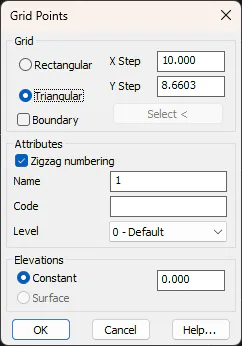
Once the parameters are validated the program requests the coordinates for a corner of the grid. Next, the second coordinate can be introduced, or, by typing "X" the direction of the X axis can be indicated, to create non-orthogonal grids. When the size of the grid is designated, the calculations of the number of points that are going to be created are displayed in the CAD status bar.
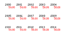
The points created are numbered successively, beginning in the first corner designated, and following the direction of the X axis.